| 56.10. Diagnostics and statistics | ||
|---|---|---|
 | Chapter 56. CTI System |  |
| 56.10. Diagnostics and statistics | ||
|---|---|---|
| | Chapter 56. CTI System | |
This section is an overview of the most frequently commands used to display the diagnostics and statistics of the CTI resources.
To show the diagnostics of the CTI Ports (ISDN Basic or Primary Rate) the following commands are used:
Shows the diagnostics of all the CTI ports.
Shows the diagnostics of a single CTI port.
To show the statistics of the CTI Ports (ISDN Basic or Primary Rate) the following commands are used:
Shows the statistics of all the CTI ports.
Shows the statistics of a single CTI port.
More information can be viewed using the following commands:
Shows the extended statistics of all the CTI ports.
Shows the extended statistics of a single CTI port.
This command reports the current situation of PRI port:
[16:46:29] ABILIS_CPX:d d ctip:1

CTIP:1   ----------------------------------------------------------------------
       USER:#                                 OPSTATE:UP          STATE:UP
       ------------------------------------------------------------------------
       CH: STATE: [Q932-STATE:] CG: [SG:]               CD: [SD:]
       ------------------------------------------------------------------------
       1   10-CONNECTED-TO      3111111111              111111117
       2   10-CONNECTED-FROM    0111111111              0
       3   10-CONNECTED-FROM    0111111111              9
       4   10-CONNECTED-FROM    0111111111              9
       5   10-CONNECTED-FROM    0111111111              1
       6   10-CONNECTED-FROM    0111111111              3
       7   10-CONNECTED-FROM    0111111111              7
       8   10-CONNECTED-TO      3311111111              111111117
       11  10-CONNECTED-TO      0311111111              111111117
       - Sapi ------- TEI -- STATE ------------ LOC-side -- REM-side-----------
         16 (X.25 )    10    00-INACTIVE        -           -
         0  (Q.931)     0    07-CONNECTED       NT          TE
       ------------------------------------------------------------------------
       ISDN-STATE:PRI-UP                  LINE-DOWN:1          SLIPS:629
       RxAlarms:NONE                      TxAlarms:NONE
Data shows that the physical layer is UP
(ISDN-STATE:PRI-UP) and the
TEI has been correctly negotiated (TEI-0,
STATE:07-CONNECTED). Several calls are present
(CONNECTED-FROM, CONNECTED-TO)
at this port and for each one the corresponding PRI channel in use
(CH:1-2-3...) is
indicated.
The meaning:
USERName of the user assigned to this port. From 1 up to 32 ASCII characters or "#". The user must be present and it must not be already assigned to another port.
OPSTATEThe operative state of the port.
STATEThe overall state of the port.
CHChannel number.
STATEChannel state.
CGCalling address.
SGCalling sub-address.
CDCalled address.
SDCalled sub-address.
SapiReferenced LAPD SAPI.
TEILAPD Currently assigned TEI.
STATELAPD driver state.
LOC-sideLocal side.
REM-sideRemote side.
ISDN-STATECTI port state:
PRI-UP;
PRI-DOWN.
LINE-DOWNNumber of state transitions from UP to DOWN.
SLIPSNumber of SLIPS detected at level 1.
RxAlarmsBitmap of current alarms in Rx direction.
TxAlarmsBitmap of current alarms in Tx direction.
This command can help to understand what is happening, in case of troubles:
[11:19:27] ABILIS_CPX:d s ctip:1CTIP:1 ---------------------------------------------------------------------- USER:# --- Cleared 154 days 02:22:53 ago, on 15/01/2018 at 08:56:39 ----------- Layer 3 Q.931 -----------|---INPUT---|--OUTPUT---|-----------|---INPUT---|--OUTPUT---| FAIL-CALL | 22148| 216|SUCC-CALL | 54128| 52978| TIME-CALL | 5606369| 5946959| ------------------------------------------------------------------------ Layer 2 Sapi 16 (X.25) TEI:10 -----------|---INPUT---|--OUTPUT---|-----------|---INPUT---|--OUTPUT---| T200-DN | | 0|T200-UP | | 0| REP | 0| 0|INFO | 0| 0| UI | 0| 0|RR | 0| 0| RNR | 0| 0|REJ | 0| 0| FRMR | 0| 0|SABME | 0| 0| UA | 0| 0|DISC | 0| 0| DM | 0| 0|N200-OVER | | 0| SHORT | 0| |LONG | 0| | UNK-SAPI | 0| |BAD-FRM | 0| | ------------------------------------------------------------------------ Layer 2 Sapi 0 (Q.931) TEI:ALL -----------|---INPUT---|--OUTPUT---|-----------|---INPUT---|--OUTPUT---| T200-DN | | 0|T200-UP | | 20| REP | 0| 0|INFO | 971089| 504465| UI | 0| 0|RR | 1683262| 2149889| RNR | 0| 0|REJ | 0| 0| FRMR | 0| 0|SABME | 0| 2| UA | 2| 0|DISC | 0| 0| DM | 0| 0|N200-OVER | | 1| SHORT | 0| |LONG | 0| | UNK-SAPI | 0| |BAD-FRM | 0| | ------------------------------------------------------------------------ Layer 1 B-Channels (HDLC) -----------|---INPUT---|--OUTPUT---|-----------|---INPUT---|--OUTPUT---| CHR | 0| 0|FRM | 0| 0| CHR-D | 0| 0|FRM-D | 0| 0| CHR-V | 0| 0|FRM-V | 0| 0| CHR-C | 0| 0|FRM-C | 0| 0| ERRORS | 0| 0| ------------------------------------------------------------------------ Layer 1 D-Channel -----------|---INPUT---|--OUTPUT---|-----------|---INPUT---|--OUTPUT---| CHR | 20981718| 16950508|FRM | 2654353| 2654356| CHR-D | 20981718| 16950508|FRM-D | 2654353| 2654356| ERRORS | 1| 0| ------------------------------------------------------------------------ Layer 1 alarms -----------|---INPUT---|--OUTPUT---|-----------|---INPUT---|--OUTPUT---| SLIPS | 629| N/A|LINE-DOWN | 1| | CRC4 | 0| 0|LOS | 1| | BAD-CODING | 4| |AIS | 0| 0| LFA | 1| |RAI | 1| 2| LMFA | 2| | ------------------------------------------------------------------------ [11:19:32] ABILIS_CPX:d se ctip:1CTIP:1 ---------------------------------------------------------------------- USER:# --- Cleared 154 days 02:22:57 ago, on 15/01/2018 at 08:56:39 ----------- Layer 3 Q.931 -----------|---INPUT---|--OUTPUT---|-----------|---INPUT---|--OUTPUT---| FAIL-CALL | 22148| 216|SUCC-CALL | 54128| 52978| TIME-CALL | 5606381| 5946963| ------------------------------------------------------------------------ Layer 2 Sapi 16 (X.25) TEI:10 -----------|---INPUT---|--OUTPUT---|-----------|---INPUT---|--OUTPUT---| T200-DN | | 0|T200-UP | | 0| REP | 0| 0|INFO | 0| 0| UI | 0| 0|RR | 0| 0| RNR | 0| 0|REJ | 0| 0| FRMR | 0| 0|SABME | 0| 0| UA | 0| 0|DISC | 0| 0| DM | 0| 0|N200-OVER | | 0| SHORT | 0| |LONG | 0| | UNK-SAPI | 0| |BAD-FRM | 0| | ------------------------------------------------------------------------ Layer 2 Sapi 0 (Q.931) TEI:0 -----------|---INPUT---|--OUTPUT---|-----------|---INPUT---|--OUTPUT---| T200-DN | | 0|T200-UP | | 20| REP | 0| 0|INFO | 971089| 504465| UI | 0| 0|RR | 1683263| 2149890| RNR | 0| 0|REJ | 0| 0| FRMR | 0| 0|SABME | 0| 2| UA | 2| 0|DISC | 0| 0| DM | 0| 0|N200-OVER | | 1| SHORT | 0| |LONG | 0| | UNK-SAPI | 0| |BAD-FRM | 0| | ------------------------------------------------------------------------ Layer 1 B-Channels (HDLC) -----------|---INPUT---|--OUTPUT---|-----------|---INPUT---|--OUTPUT---| CHR | 0| 0|FRM | 0| 0| CHR-D | 0| 0|FRM-D | 0| 0| CHR-V | 0| 0|FRM-V | 0| 0| CHR-C | 0| 0|FRM-C | 0| 0| ERRORS | 0| 0| | | | D-ABORT | | 0|D-LONG | 0| 0| D-TXUND | | 0|D-SHORT | | 0| D-LOST | 0| | | | | V-ABORT | | 0|V-LONG | 0| 0| V-TXUND | | 0|V-SHORT | | 0| V-LOST | 0| | | | | C-ABORT | | 0|C-LONG | 0| 0| C-TXUND | | 0|C-SHORT | | 0| C-LOST | 0| | | | | ABORT | 0| |UNALIGNED | 0| | BAD-FCS | 0| |SHORT | 0| | CHR-OVR | 0| |FRM-OVR | 0| | ------------------------------------------------------------------------ Layer 1 D-Channel -----------|---INPUT---|--OUTPUT---|-----------|---INPUT---|--OUTPUT---| CHR | 20981722| 16950512|FRM | 2654354| 2654357| CHR-D | 20981722| 16950512|FRM-D | 2654354| 2654357| ERRORS | 1| 0| | | | D-ABORT | | 0|D-LONG | 0| 0| D-TXUND | | 0|D-SHORT | | 0| D-LOST | 0| | | | | ABORT | 1| |UNALIGNED | 0| | BAD-FCS | 0| |SHORT | 0| | CHR-OVR | 0| |FRM-OVR | 0| | ------------------------------------------------------------------------ Layer 1 alarms -----------|---INPUT---|--OUTPUT---|-----------|---INPUT---|--OUTPUT---| SLIPS | 629| N/A|LINE-DOWN | 1| | CRC4 | 0| 0|LOS | 1| | BAD-CODING | 4| |AIS | 0| 0| LFA | 1| |RAI | 1| 2| LMFA | 2| | ------------------------------------------------------------------------
With reference to the shown interval of time («Cleared 154 days 02:22:57 ago») these counters show the number of:
FAIL-CALL | Failed incoming/outgoing voice calls. |
SUCC-CALL | The sum of all calls. |
TIME-CALL | The sum of established incoming/outgoing voice calls duration. |
T200-DN | Number of T200 out when disconnected. |
T200-UP | Number of T200 out when connected. |
REP | Repeated incoming/outgoing frames. |
INFO | Incoming/outgoing info frames. |
UI | Incoming/outgoing unnumbered info frames. |
RR | Incoming/outgoing unnumbered RR frames. |
RNR | Incoming/outgoing unnumbered RNR frames. |
REJ | Incoming/outgoing unnumbered REJ frames. |
FRMR | Incoming/outgoing unnumbered FRMR frames. |
SABME | Incoming/outgoing unnumbered SABME frames. |
UA | Incoming/outgoing unnumbered UA frames. |
DISC | Incoming/outgoing unnumbered DISC frames. |
DM | Incoming/outgoing unnumbered DM frames. |
N200-OVER | Expired retries in connected. |
SHORT | Too short incoming/outgoing frames. |
LONG | Too long incoming/outgoing frames. |
UNK-SAPI | Incoming frames with unknown address field. |
BAD-FRM | Number of incoming frames with unknown control field. |
CHR | Total incoming/outgoing characters from/into line. |
CHR-D/V/C | Total incoming/outgoing DATA/VOICE/LINK-CHECK characters from/into line. |
FRM | Total incoming/outgoing frames from/into line. |
FRM-D/V/C | Total incoming/outgoing DATA/VOICE/LINK-CHECK frames from/into line. |
ERRORS | The sum of all errors. |
D/V/C-ABORT | Incoming/outgoing DATA/VOICE/LINK-CHECK frames aborted. |
D/V/C-TXUND | DATA/VOICE/LINK-CHECK transmission underrun. |
D/V/C-LOST | Lost DATA/VOICE/LINK-CHECK frames: buffer is full. |
D/V/C-LONG | Too long incoming/outgoing DATA/VOICE/LINK-CHECK frames. |
D/V/C-SHORT | Too short incoming/outgoing DATA/VOICE/LINK-CHECK frames. |
ABORT | Incoming/outgoing frames aborted. |
UNALIGNED | Received unaligned frames. |
BAD-FCS | Received frames with BAD FCS. |
SHORT | Received too short frames. |
CHR-OVR | Received characters overruns. |
FRM-OVR | Received frames overruns. |
SLIPS | SLIPS detected at level 1. |
LINE-DOWN | Number of state transitions from UP to DOWN. |
CRC4 | IN: incoming multiframes with a bad CRC4. OUT: outgoing multiframes indicating a "remote CRC4 error". |
LOS | Incoming "Loss of signal". |
BAD-CODING | Coding (hdb3) errors in the received signal. |
AIS | Incoming/outgoing "alarm information signal". |
LFA | Incoming "loss of frame alignment". |
RAI | Incoming/outgoing "remote alarm information". |
LMFA | Incoming "loss of multiframe alignment". |
This command reports the current situation of BRI port:
[15:45:27] ABILIS_CPX:d d ctip:38

CTIP:38  ----------------------------------------------------------------------
       Port_to_Telecom
       USER:#                                 OPSTATE:UP          STATE:UP
       ------------------------------------------------------------------------
       CH: STATE: [Q932-STATE:] CG: [SG:]               CD: [SD:]
       ------------------------------------------------------------------------
                         *** All channels disconnected ***
       - Sapi ------- TEI -- STATE ------------ LOC-side -- REM-side-----------
         16 (X.25 )    10    00-INACTIVE        -           -
         0  (Q.931)    92    07-CONNECTED       TE          NT
       ------------------------------------------------------------------------
       ISDN-STATE:F7-READY                LINE-DOWN:1          SLIPS:N/A
Data shows that the physical layer is UP
(ISDN-STATE:F7-READY) and the TEI has been
correctly negotiated (TEI-102,
STATE:07-CONNECTED). The message “*** All
channels disconnected ***” indicates that no calls are
connected.
The meaning:
USERName of the user assigned to this port. From 1 up to 32 ASCII characters or "#". The user must be present and it must not be already assigned to another port.
OPSTATEThe operative state of the port.
STATEThe overall state of the port.
CHChannel number.
STATEChannel state.
CGCalling address.
SGCalling sub-address.
CDCalled address.
SDCalled sub-address.
SapiReferenced LAPD SAPI.
TEILAPD Currently assigned TEI.
STATELAPD driver state.
LOC-sideLocal side.
REM-sideRemote side.
ISDN-STATEBRI-TE port state:
F3-INACT - TE inactive, no power
feeding;
F3-INACT2 - TE power feed,
waiting for INFO 0;
F3-INACT3 - pending
deactivation;
F4-DOWN - pending activation, TE
is waiting for signal;
F5-DOWN - unsynchronised, signal
received, synchronisation;
F6-DOWN - synchronised, ready for
receiving;
F7-READY - activated,
working;
F8-DOWN - loss of frame
alignment.
BRI-NT port state:
G1-DEACTIVATED;
G2-PENDING_ACTIVATION;
G2-LOST_FRAMING;
G3-READY;
G3-ACTIVATED_BLOCKED;
G4-PENDING_DEACTIVATION;
G4-WAIT_DEACTIVATION.
LINE-DOWNNumber of state transitions from UP to DOWN.
SLIPSNumber of SLIPS detected at level 1.
This command can help to understand what is happening, in case of troubles:
[15:55:24] ABILIS_CPX:d s ctip:31

CTIP:31  ----------------------------------------------------------------------
       to_PBX
       USER:#
       --- Cleared 0 days 19:57:53 ago, on 16/06/2015 at 12:23:35 -------------
       Layer 3 Q.931
       -----------|---INPUT---|--OUTPUT---|-----------|---INPUT---|--OUTPUT---|
       FAIL-CALL  |          0|          0|SUCC-CALL  |          0|          0|
       TIME-CALL  |          0|          0|
       ------------------------------------------------------------------------
       Layer 2 Sapi 16 (X.25)  TEI:10
       -----------|---INPUT---|--OUTPUT---|-----------|---INPUT---|--OUTPUT---|
       T200-DN    |           |          0|T200-UP    |           |          0|
       REP        |          0|          0|INFO       |          0|          0|
       UI         |          0|          0|RR         |          0|          0|
       RNR        |          0|          0|REJ        |          0|          0|
       FRMR       |          0|          0|SABME      |          0|          0|
       UA         |          0|          0|DISC       |          0|          0|
       DM         |          0|          0|N200-OVER  |           |          0|
       SHORT      |          0|           |LONG       |          0|           |
       UNK-SAPI   |          0|           |BAD-FRM    |          0|           |
       ------------------------------------------------------------------------
       Layer 2 Sapi 0  (Q.931) TEI:ALL
       -----------|---INPUT---|--OUTPUT---|-----------|---INPUT---|--OUTPUT---|
       T200-DN    |           |      35765|T200-UP    |           |          0|
       REP        |          0|          0|INFO       |          0|          0|
       UI         |          0|          0|RR         |          0|          0|
       RNR        |          0|          0|REJ        |          0|          0|
       FRMR       |          0|          0|SABME      |          0|          0|
       UA         |          0|          0|DISC       |          0|          0|
       DM         |          0|          0|N200-OVER  |           |          0|
       SHORT      |          0|           |LONG       |          0|           |
       UNK-SAPI   |          0|           |BAD-FRM    |          0|           |
       ------------------------------------------------------------------------
       Layer 1 B-Channels (HDLC)
       -----------|---INPUT---|--OUTPUT---|-----------|---INPUT---|--OUTPUT---|
       CHR        |          0|          0|FRM        |          0|          0|
       CHR-D      |          0|          0|FRM-D      |          0|          0|
       CHR-V      |          0|          0|FRM-V      |          0|          0|
       CHR-C      |          0|          0|FRM-C      |          0|          0|
       ERRORS     |          0|          0|
       ------------------------------------------------------------------------
       Layer 1 D-Channel
       -----------|---INPUT---|--OUTPUT---|-----------|---INPUT---|--OUTPUT---|
       CHR        |          0|          0|FRM        |          0|          0|
       CHR-D      |          0|          0|FRM-D      |          0|          0|
       ERRORS     |          0|          0|
       ------------------------------------------------------------------------
       Layer 1 alarms
       -----------|---INPUT---|--OUTPUT---|-----------|---INPUT---|--OUTPUT---|
       SLIPS      |        N/A|        N/A|LINE-DOWN  |          0|           |
       ------------------------------------------------------------------------
The data “Cleared DDD:HH:MM:SS ago, at DD/MM/YYYY HH:MM:SS” shows the time interval elapsed from the last reset of statistics (in the format “days:hours:minutes:seconds”) and date/time of its execution (in the format “day:month:year” and “hours:minutes:seconds”).
All the other statistics present give detailed and sensitive information about the connection between Abilis and the other devices (i.e. PABX, the ISDN line…). The statistics regard all the three levels of ISO-OSI model:
The physical layer (Layer 1) which shows the number of physical errors, the characters both on the D-Channel and B-Channels and so on;
![[Note]](../images/note.png) | Note |
|---|---|
The Layer 1 B-Channels (HDLC) shows the counts of HDLC packets, what in practice is the calls type:DATA used by PV/NPV/AIPT with Abilis back-up. |
The LAPD level (Layer 2) which shows the number of packets that the devices exchange;
| Note |
|---|---|
On the Layer 2 Sapi 0 (Q.931), if the number of DISC packets increases in input it means what this line is a MP (MultiPoint). |
The Q.931 level (Layer 3) which the information about the overall duration of the connection or the number of successful incoming calls over all the channels.
Example: extended statistics for the previous ISDN BRI port.
[15:55:40] ABILIS_CPX:d se ctip:31

CTIP:31  ----------------------------------------------------------------------
       to_PBX
       USER:#
       --- Cleared 0 days 19:59:41 ago, on 16/06/2015 at 12:23:36 -------------
       Layer 3 Q.931
       -----------|---INPUT---|--OUTPUT---|-----------|---INPUT---|--OUTPUT---|
       FAIL-CALL  |          0|          0|SUCC-CALL  |          0|          0|
       TIME-CALL  |          0|          0|
       ------------------------------------------------------------------------
       Layer 2 Sapi 16 (X.25)  TEI:10
       -----------|---INPUT---|--OUTPUT---|-----------|---INPUT---|--OUTPUT---|
       T200-DN    |           |          0|T200-UP    |           |          0|
       REP        |          0|          0|INFO       |          0|          0|
       UI         |          0|          0|RR         |          0|          0|
       RNR        |          0|          0|REJ        |          0|          0|
       FRMR       |          0|          0|SABME      |          0|          0|
       UA         |          0|          0|DISC       |          0|          0|
       DM         |          0|          0|N200-OVER  |           |          0|
       SHORT      |          0|           |LONG       |          0|           |
       UNK-SAPI   |          0|           |BAD-FRM    |          0|           |
       ------------------------------------------------------------------------
       Layer 2 Sapi 0  (Q.931)  TEI:0
       -----------|---INPUT---|--OUTPUT---|-----------|---INPUT---|--OUTPUT---|
       T200-DN    |           |      35820|T200-UP    |           |          0|
       REP        |          0|          0|INFO       |          0|          0|
       UI         |          0|          0|RR         |          0|          0|
       RNR        |          0|          0|REJ        |          0|          0|
       FRMR       |          0|          0|SABME      |          0|          0|
       UA         |          0|          0|DISC       |          0|          0|
       DM         |          0|          0|N200-OVER  |           |          0|
       SHORT      |          0|           |LONG       |          0|           |
       UNK-SAPI   |          0|           |BAD-FRM    |          0|           |
       ------------------------------------------------------------------------
       Layer 1 B-Channels (HDLC)
       -----------|---INPUT---|--OUTPUT---|-----------|---INPUT---|--OUTPUT---|
       CHR        |          0|          0|FRM        |          0|          0|
       CHR-D      |          0|          0|FRM-D      |          0|          0|
       CHR-V      |          0|          0|FRM-V      |          0|          0|
       CHR-C      |          0|          0|FRM-C      |          0|          0|
       ERRORS     |          0|          0|           |           |           |
       D-ABORT    |           |          0|D-LONG     |          0|          0|
       D-TXUND    |           |          0|D-SHORT    |           |          0|
       D-LOST     |          0|           |           |           |           |
       V-ABORT    |           |          0|V-LONG     |          0|          0|
       V-TXUND    |           |          0|V-SHORT    |           |          0|
       V-LOST     |          0|           |           |           |           |
       C-ABORT    |           |          0|C-LONG     |          0|          0|
       C-TXUND    |           |          0|C-SHORT    |           |          0|
       C-LOST     |          0|           |           |           |           |
       ABORT      |          0|           |UNALIGNED  |          0|           |
       BAD-FCS    |          0|           |SHORT      |          0|           |
       CHR-OVR    |          0|           |FRM-OVR    |          0|           |
       ------------------------------------------------------------------------
       Layer 1 D-Channel
       -----------|---INPUT---|--OUTPUT---|-----------|---INPUT---|--OUTPUT---|
       CHR        |          0|          0|FRM        |          0|          0|
       CHR-D      |          0|          0|FRM-D      |          0|          0|
       ERRORS     |          0|          0|           |           |           |
       D-ABORT    |           |          0|D-LONG     |          0|          0|
       D-TXUND    |           |          0|D-SHORT    |           |          0|
       D-LOST     |          0|           |           |           |           |
       ABORT      |          0|           |UNALIGNED  |          0|           |
       BAD-FCS    |          0|           |SHORT      |          0|           |
       CHR-OVR    |          0|           |FRM-OVR    |          0|           |
       ------------------------------------------------------------------------
       Layer 1 alarms
       -----------|---INPUT---|--OUTPUT---|-----------|---INPUT---|--OUTPUT---|
       SLIPS      |        N/A|        N/A|LINE-DOWN  |          0|           |
       ------------------------------------------------------------------------
The information displayed are the same as previously, but more
detailed and splitted (i.e. The generic “ERRORS” is
subdivided in D-ABORT,
D-TXUND, ABORT,
BAD-FCS…).
With reference to the shown interval of time («Cleared 0 days 19:59:41 ago») these counters show the number of:
FAIL-CALL | Failed incoming/outgoing voice calls. |
TIME-CALL | The sum of established incoming/outgoing voice calls duration. |
SUCC-CALL | The sum of all calls. |
T200-DN | Number of T200 out when disconnected. |
T200-UP | Number of T200 out when connected. |
REP | Repeated incoming/outgoing frames. |
INFO | Incoming/outgoing info frames. |
UI | Incoming/outgoing unnumbered info frames. |
RR | Incoming/outgoing unnumbered RR frames. |
RNR | Incoming/outgoing unnumbered RNR frames. |
REJ | Incoming/outgoing unnumbered REJ frames. |
FRMR | Incoming/outgoing unnumbered FRMR frames. |
SABME | Incoming/outgoing unnumbered SABME frames. |
UA | Incoming/outgoing unnumbered UA frames. |
DISC | Incoming/outgoing unnumbered DISC frames. |
DM | Incoming/outgoing unnumbered DM frames. |
N200-OVER | Expired retries in connected. |
SHORT | Too short incoming/outgoing frames. |
LONG | Too long incoming/outgoing frames. |
UNK-SAPI | Incoming frames with unknown address field. |
BAD-FRM | Number of incoming frames with unknown control field. |
CHR | Total incoming/outgoing characters from/into line. |
CHR-D/V/C | Total incoming/outgoing DATA/VOICE/LINK-CHECK characters from/into line. |
FRM | Total incoming/outgoing frames from/into line. |
FRM-D/V/C | Total incoming/outgoing DATA/VOICE/LINK-CHECK frames from/into line. |
ERRORS | The sum of all errors. |
D/V/C-ABORT | Incoming/outgoing DATA/VOICE/LINK-CHECK frames aborted. |
D/V/C-TXUND | DATA/VOICE/LINK-CHECK transmission underrun. |
D/V/C-LOST | Lost DATA/VOICE/LINK-CHECK frames: buffer is full. |
D/V/C-LONG | Too long incoming/outgoing DATA/VOICE/LINK-CHECK frames. |
D/V/C-SHORT | Too short incoming/outgoing DATA/VOICE/LINK-CHECK frames. |
ABORT | Incoming/outgoing frames aborted. |
UNALIGNED | Received unaligned frames. |
BAD-FCS | Received frames with BAD FCS. |
SHORT | Received too short frames. |
CHR-OVR | Received characters overruns. |
FRM-OVR | Received frames overruns. |
SLIPS | SLIPS detected at level 1. |
LINE-DOWN | Number of state transitions from UP to DOWN. |
This command reports the current situation of the POTS port:
[14:58:51] ABILIS_CPX:d d ctip:101CTIP:101 ---------------------------------------------------------------------- phone_1 USER:11 OPSTATE:UP STATE:UP ------------------------------------------------------------------------ CH: STATE: [Q932-STATE:] CG: [SG:] CD: [SD:] ------------------------------------------------------------------------ 1 10-CONNECTED-FROM 767 777 ------------------------------------------------------------------------ POTS-STATE:OFF-HOOK TONE:NONE COUNTRY:IT TRACE:777 [14:58:59] ABILIS_CPX:d de ctip:101CTIP:101 ---------------------------------------------------------------------- phone_1 USER:11 OPSTATE:UP STATE:UP ------------------------------------------------------------------------ CH: STATE: [Q932-STATE:] CG: [SG:] CD: [SD:] ------------------------------------------------------------------------ 1 10-CONNECTED-FROM 767 777 ------------------------------------------------------------------------ POTS-STATE:OFF-HOOK TONE:NONE COUNTRY:IT TRACE:777 SENSING:YES I-LOOP:28 mA R-LOOP:301 Ohm VS:-22.186 V VA(Tip):-4.109 V VB(Ring):-12.866 V VAB:+8.738 V IG-COUNTRY:8 IG-CURRENT:8 OG-COUNTRY:-9 OG-CURRENT:-9
The meaning:
USERName of the user assigned to this port. From 1 up to 32 ASCII characters or "#". The user must be present and it must not be already assigned to another port.
OPSTATEThe operative state of the port.
STATEThe overall state of the port.
POTS-STATEThe overall state of the POTS connection:
ON-HOOK - The port HOOK is
ON.
RINGING - The phone is RINGING.
State is RINGING during both actual
ring and pause. The phone is still
ON-HOOK in this state.
OFF-HOOK - The port HOOK is
OFF.
DOWN - The port is
administratively deactivated by
OPSTATE:DOWN.
STAND-BY - The port is in
stand-by mode, which is a mode with limited power
consumption and an automatic recovery to normal operation
when telephone goes off-hook or an incoming call has to be
delivered. This functionality is currently not supported,
but it may be supported in the future.
FAILED - The port is in FAILED
state, because of detected errors during the
initialisation or running.
HOTEL-ALARM - Hotel ALARM is
pressed.
TONEThe type of the tone currently generated by the tone generator:
NONE - The tone generator doesn't
generate tone.
DIALLING - The DIALLING tone is
generated by the tone generator.
RINGING - The RINGING tone is
generated by the tone generator.
BUSY - The BUSY tone is generated
by the tone generator.
DISCONNECTING - The DISCONNECTING
tone is generated by the tone generator.
HOLD - The HOLD tone is generated
by the tone generator.
MENU - The MENU tone is generated
by the tone generator.
COUNTRYCurrently used country register set - from WinSLAC.
TRACEThe last 40 DTMF codes and FLASH events detected by the port during the last call.
SENSINGState of the sensing feature. If sensing is disabled, the subsequent diagnostics (measured V, A, Ohms) are invalid, and CP has to display "N/A" in their fields.
I-LOOPMeasures the loop current, in mA. Legerity names it
"metallic current" because this measure takes care also of the
leakage currents toward ground of either tip or ring or both,
by removing it. The result is the real current which flows
between telephone (metallic) wires at the telephone connector.
Leakage phenomena are usually not present in short lines, e.g.
When pots is used as a local PABX with few meters telephone
wires, but are normally present on real telco lines, where
kilometres of wire is used, where insulation on kilometres
long wire is not negligible and degrades with the age of the
cables. Remember that VoSLIC is a device suitable for long
haul telco analogue lines. Typical values: in
ON-HOOK state --> 1,1 mA, in
OFF-HOOK state --> 28,2 mA.
R-LOOPThe resistance of the analogue loop connected to the
VoSLIC analogue interface. Typical values: in
ON-HOOK state --> 7,9 kOhms, in
OFF-HOOK state --> 0,3 kOhms.
VSPower supply voltage as offered by switching power
supply. This voltage changes between
ON-HOOK, RINGING and
OFF-HOOK states. Typical values: in
ON-HOOK state --> -63,5 V, in
OFF-HOOK state --> -25,3 V.
VA(Tip)The voltage of the A (tip) wire of the VoSLIC analogue
interface, measured respect to ground. Typical values: in
ON-HOOK state --> -4 V, in
OFF-HOOK state --> -3…6 V
VB(Ring)The voltage of the B (ring) wire of the VoSLIC analogue
interface, measured respect to ground. Typical values: in
ON-HOOK state --> -53 V, in
OFF-HOOK state --> -13…-14 V
VABThis is voltage between two wires (A(tip) and B(ring))
of the VoSLIC analogue interface. Typical values: in
ON-HOOK state --> 49,4 V, in
OFF-HOOK state --> 8,8 V
IG-COUNTRYTotal Input gain ( voslic/voslac "X" path) read from configured country file. It includes analogue gain.
IG-CURRENTTotal Input gain (voslic/voslac "X" path) currently in use. It includes analogue gain.
OG-COUNTRYTotal Output gain (voslic/voslac "R" path) read from configured country file. It includes analogue gain.
OG-CURRENTTotal Output gain (voslic/voslac "R" path) currently in use. It includes analogue gain.
This command can help to understand what is happening, in case of troubles:
[14:01:32] ABILIS_CPX:d s ctip:101CTIP:101 ---------------------------------------------------------------------- phone_1 USER:11 --- Cleared 12 days 01:20:43 ago, on 06/06/2018 at 12:40:55 ------------ Layer 3 Q.931 -----------|---INPUT---|--OUTPUT---|-----------|---INPUT---|--OUTPUT---| FAIL-CALL | 46| 30|SUCC-CALL | 54| 52| TIME-CALL | 9229| 16193| ------------------------------------------------------------------------ Layer 1 POTS -----------|-----------|-----------|-----------|-----------|-----------| ON-HOOK | 151|FLASH | 7|GND-KEY-ON | 0| OFF-HOOK | 151|FLASH-SHORT| 0|GND-KEY-OFF| 0| CLIP | 83|FAX-MOD | 0|HOTEL-ALM | 0| DTMF | 302|TESTS | 0|ERRORS | 0| ------------------------------------------------------------------------ [14:01:38] ABILIS_CPX:d se ctip:101CTIP:101 ---------------------------------------------------------------------- phone_1 USER:11 --- Cleared 12 days 01:20:46 ago, on 06/06/2018 at 12:40:56 ------------ Layer 3 Q.931 -----------|---INPUT---|--OUTPUT---|-----------|---INPUT---|--OUTPUT---| FAIL-CALL | 46| 30|SUCC-CALL | 54| 52| TIME-CALL | 9229| 16193| ------------------------------------------------------------------------ Layer 1 POTS -----------|-----------|-----------|-----------|-----------|-----------| ON-HOOK | 151|FLASH | 7|GND-KEY-ON | 0| OFF-HOOK | 151|FLASH-SHORT| 0|GND-KEY-OFF| 0| CLIP | 83|FAX-MOD | 0|HOTEL-ALM | 0| DTMF | 302|TESTS | 0|ERRORS | 0| DTMF-ERR | 0|TEMP-OVL | 0|VS-FAIL | 0| DTMF-OVR | 0|CLK-FAIL | 0|DC-FAULT | 0| AC-FAULT | 0| ------------------------------------------------------------------------
With reference to the shown interval of time («Cleared 12 days 01:20:43 ago») these counters show the number of:
FAIL-CALL | Failed incoming/outgoing voice calls. |
TIME-CALL | The sum of established incoming/outgoing voice calls duration. |
SUCC-CALL | The sum of all calls. |
ON-HOOK | ON-HOOK events detected by the port event detector. |
OFF-HOOK | OFF-HOOK events detected by the port event detector. |
FLASH | FLASH events detected by the port event detector. |
FLASH-SHORT | Too short FLASH events detected by the event detector. |
GND-KEY-ON | Detected ground key ON events, based on GNDKEY interrupt. |
GND-KEY-OFF | Detected ground key OFF events, based on GNDKEY interrupt. |
CLIP | CLIP sequences generated by the port. |
FAX-MOD | Detected modem or fax tones (interrupt). |
HOTEL-ALM | Detected hotel alarms. |
DTMF | DTMF numbers delivered into the upper layer. |
DTMF-ERR | Incorrect DTMF codes read from VoSLAC chip. |
DTMF-OVR | DTMF fifo overflows. |
TESTS | Executed tests (special test available on VoSLAC/VoSLIC chips) (interrupt).e. |
TEMP-OVL | Detected thermal overload events (interrupt). |
CLK-FAIL | Detected clock failures. |
ERRORS | Cumulative counter of all errors. |
VS-FAIL | Failures detected in the power supply of the analogue section (VS). |
DC-FAULT | Detected DC faults (interrupt). |
AC-FAULT | Detected AC faults (interrupt). |
This command reports the current situation of the device:
[09:21:45] ABILIS_CPX:d d ctip:502

CTIP:502 ----------------------------------------------------------------------
       SIM_1)
       USER:#                                 OPSTATE:UP          STATE:UP
       ------------------------------------------------------------------------
       CH: STATE: [Q932-STATE:] CG: [SG:]               CD: [SD:]
       ------------------------------------------------------------------------
                         *** All channels disconnected ***
       ------------------------------------------------------------------------
       VOICE-STATE:READY       PDN-STATE:READY         SMS-STATE:READY
       ------------------------------------------------------------------------
       NET:WIND                NET-MODE:GSM            ROAMING:NO
       SIGNAL:22               SIGNAL-dbm:-69          RXQUAL:0
       IMEI:357396012653490    IMSI:222881451579032    SIM:8939883345002210328
       SMSC:+393205858500      CODEC-ISO-BW:1304000    SIM-SEL:FIX-SIM-A
       CELL-MODEL:SIM5210      CELL-VER:V1.92          CELL-FEAT:VOICE,DATA,SMS
       CELL:CONNECTED          CELL-STATE:READY        CELL-ERR:NONE
       CODEC:CONNECTED         CODEC-STATE:READY       CODEC-ERR:NONE
       CONTROL:CONNECTED       CONTROL-STATE:READY     CONTROL-ERR:NONE
The meaning:
USERName of the user assigned to this port. From 1 up to 32 ASCII characters or "#". The user must be present and it must not be already assigned to another port.
OPSTATEThe overall state of the port.
VOICE-STATEThe overall state of the GSM VOICE connection:
DOWN - Not ready to place or
receive VOICE calls, either because of missing connection
to the network or for some administratively or
configuration reasons.
READY - Ready to place and
receive VOICE calls.
IN-USE - A VOICE connection is
ongoing or active.
PDN-STATEThe overall state of the PDN (Packet Data Network) connection:
DOWN - Not ready to attach to
PDN, either because of missing connection to the network
or for some administratively or configuration
reasons.
READY - Ready to attach to
PDN.
IN-USE - A PDN connection is
ongoing or active.
BLOCKED - When the USB MODEM
interface is blocked (The state should not survive too
long, because safety timer restarts whole USB device after
enter this state and timeout).
SMS-STATEThe overall state of the SMS channel:
DOWN - Ready to send/receive
SMSs.
READY - Ready to send/receive
SMSs.
NETThe currently used GSM network name.
ROAMINGShows if the currently used UMTS/GSM network is ROAMING type:
N/A - The ROAMING diagnostic
isn't valid (when NO SIM card inserted, when no network
registered etc).
NO - The used network isn't
ROAMING type.
YES - The used network is ROAMING
type.
NET-MODEShows if the currently used network is GSM, UMTS or LTE.
SIGNALSignal quality (0 = -113 dBm or less, 1..30 = -111.. -53 dBm, 31 = -51 dBm, or greater 99 = not known or not detectable, 100 = N/A value when the device isn't connected)
RXQUALThe value of BER (bit error rate) of the existing call.
IMEIInternational Mobile Equipment Identity number.
IMSIInternational Mobile Subscriber Identity number.
SIMSIM card identification number.
SMSCSMS Center number.
CODEC-ISO-BWIndicates the bandwidth of the AUDIO-CODEC ISO interface.
CELL-MODELThe CELL device model currently used by the port:
N/A - No device connected.
SIM5210 - SimCom 5210 module
connected (UMTSBOX2 2011).
SIM5218 - SimCom 5218 module
connected (UMTSBOX2 2012).
UD7200 - UMTSKEY module
connected.
SIM7230E - SimCom 7230E module
connected.
SIM7250E - SimCom 7250E module
connected.
CELLShows if the hot-pluggable device is connected or not:
DISCONNECTED - Not connected to
CPX.
CONNECTED - Connected to
CPX.
UNAVAIL - No Gsm module is
available for this GSM port (USB subsystem decides about
the availability).
CELL-STATEShows the state of the USB interface of the GSM USB module:
INIT - Wait for
initialisation.
READY - Completely initialised
and ready to use.
FAILED - Failed because of
serious troubles detected on the USB bus.
CELL-ERRShows the reason of the not READY GSM module:
NONE - No error detected, the GSM
module works fine.
N/A - Not applicable error, the
error is given by values in GsmUsb and GsmUsbState values
whose are three states and cannot be expressed by this two
state diagnostic. Usually when GSM device is disconnected
or its handle isn't available.
USB-NO-RESP - USB RTU_NO_RESPONSE
error was detected.
USB-OVERCUR - USB RTU_OVERCURRENT
error was detected.
USB-NO-BW - USB RTU_BANDWIDTH
error was detected.
NO-COM - AT interface doesn't
work, detected by the At interface watchdog.
NO-SIM - No SIM card is inserted
into the module.
SIM-LOCK - The CME-ERROR: 252
(SIM BLOCKED) was detected during the checking of the PIN
protection state.
SIM-ERR - The CME-ERROR:
different from 252 was detected during the checking of the
PIN protection state.
PIN - Waits for PIN enter, the
left number of attempts 2 or 1. When the 3 attempts are
available the PIN from port configuration is automatically
entered.
PUK - Waits for PUK enter.
PIN2 - Waits for PIN2
enter.
PUK2 - Waits for PUK2
enter.
NO-SIG - No GSM signal is
available. The AT+CSQ command returns the value 99.
NO-NET - The GSM network isn't
available.
NO-REG - The GSM module isn't
registered into the network.
UNKNOWN - Unknown or not handled
error.
CODECShows if the hot-pluggable device is connected or not:
DISCONNECTED - The AUDIO module
is not connected to CPX.
CONNECTED - The AUDIO module is
connected to CPX.
UNAVAIL - No AUDIO module is
available for this GSM port (USB subsystem decides about
the availability).
INACTIVE - The AUDIO device isn't
available because of inactivating state set by S
INACT command.
CODEC-STATEShows the state of the USB interface of the CODEC module:
INIT - Wait for
initialisation.
READY - Completely initialised
and ready to use.
FAILED - Failed because of
serious troubles detected on the USB bus.
CODEC-ERRShows the reason of the not READY GSM codec:
NONE - No error detected, the GSM
codec works fine.
USB-OVERCUR - USB RTU_OVERCURRENT
error was detected.
USB-NO-BW - USB RTU_BANDWIDTH
error was detected.
N/A - Not applicable error, the
error is given by values in GsmUsb and GsmUsbState values
whose are three states and cannot be expressed by this two
state diagnostic.
CONTROLShows if the hot-pluggable device is connected or not.
CONTROL-STATEShows the state of the USB interface of the CONTROL (PIC) module.
CONTROL-ERRShows the reason of the not READY GSM CONTROL (PIC).
Diagnostics of a CTI GSM port when a call is running:
[09:23:17] ABILIS_CPX:d d ctip:502

CTIP:502 ----------------------------------------------------------------------
       SIM_xxxxxxxxxx
       USER:#                                 OPSTATE:UP          STATE:UP
       ------------------------------------------------------------------------
       CH: STATE: [Q932-STATE:] CG: [SG:]               CD: [SD:]
       ------------------------------------------------------------------------
       1   07-LOC-ALERT         779                     xxxxxxxxxx
       ------------------------------------------------------------------------
       VOICE-STATE:IN-USE      PDN-STATE:READY         SMS-STATE:READY
       ------------------------------------------------------------------------
       NET:WIND                NET-MODE:GSM            ROAMING:NO
       SIGNAL:22               SIGNAL-dbm:-69          RXQUAL:0
       IMEI:357396012653490    IMSI:222881451579032    SIM:8939883345002210328
       SMSC:+393205858500      CODEC-ISO-BW:1304000    SIM-SEL:FIX-SIM-A
       CELL-MODEL:SIM5210      CELL-VER:V1.92          CELL-FEAT:VOICE,DATA,SMS
       CELL:CONNECTED          CELL-STATE:READY        CELL-ERR:NONE
       CODEC:CONNECTED         CODEC-STATE:READY       CODEC-ERR:NONE
CONTROL:CONNECTED CONTROL-STATE:READY CONTROL-ERR:NONE![[Tip]](../images/tip.png) | Tip |
|---|---|
CODEC-ISO-BW shows the USB Isochronous bandwidth reserved on the USB controller to serve the CTIP. The audio codec always reserves the bandwidth of TWO CTIP even if one is disabled. |
This is what appears in the CTIR Connection (from PBX port group to GSM gateway):
[12:06:44] ABILIS_CPX:d ctic

SES  ID   Type Input    Output   PR  State  Cgi (Calling In)    Cdo (Called Out)
---- ---- ---- -------- -------- --- ------ ------------------- --------------------
2    2    TR   G1       502      3   ACTIVE 711                 3482233445
Scanning available networks.
Example of NETSCAN:
[10:54:26] ABILIS_CPX:d d ctip:501 netscanTHE COMMAND WILL SEARCH ALL AVAILABLE NETWORKs. THIS OPERATION MAY TAKE FEW MINUTES. PROCEED ANYWAY (N/Y)?yCTIP:501 ---------------------------------------------------------------------- SIM_xxxxxxxxxx USER:# OPSTATE:UP STATE:UP ------------------------------------------------------------------------ CH: STATE: [Q932-STATE:] CG: [SG:] CD: [SD:] ------------------------------------------------------------------------ *** All channels disconnected *** ------------------------------------------------------------------------ VOICE-STATE:READY PDN-STATE:READY SMS-STATE:READY ------------------------------------------------------------------------ NET:WIND NET-MODE:GSM ROAMING:NO SIGNAL:22 SIGNAL-dbm:-69 RXQUAL:0 IMEI:357396012653300 IMSI:222881672196219 SIM:8939880367011211389 SMSC:+393205858500 CODEC-ISO-BW:1304000 SIM-SEL:FIX-SIM-A CELL-MODEL:SIM5210 CELL-VER:V1.92 CELL-FEAT:VOICE,DATA,SMS CELL:CONNECTED CELL-STATE:READY CELL-ERR:NONE CODEC:CONNECTED CODEC-STATE:READY CODEC-ERR:NONE CONTROL:CONNECTED CONTROL-STATE:READY CONTROL-ERR:NONE - Available Networks --------------------------------------------------- Status: Name: Code: Mode: CURRENT WIND 22288 GSM AVAILABLE WIND 22288 UMTS AVAILABLE 3ITA 22299 UMTS FORBIDDEN OMNITEL 22210 GSM FORBIDDEN OMNITEL 22210 UMTS FORBIDDEN TIM 22201 UMTS FORBIDDEN TIM 22201 GSM
| Note |
|---|---|
If NETSCAN cannot be executed for any reason, e.g. because there is an active call or the module is disconnected, the message *** CANNOT EXECUTE NETSCAN *** is printed. |
This command can help to understand what is happening, in case of troubles:
[16:14:19] ABILIS_CPX:d s ctip:501

CTIP:501 ----------------------------------------------------------------------
       SIM-1
       USER:#
       --- Cleared 0 days 19:47:27 ago, on 14/05/2015 at 19:23:22 -------------
       Layer 3 Q.931
       -----------|---INPUT---|--OUTPUT---|-----------|---INPUT---|--OUTPUT---|
       FAIL-CALL  |          0|          0|SUCC-CALL  |          2|          0|
       TIME-CALL  |         48|          0|
       ------------------------------------------------------------------------
       Layer 2 PDN
       -----------|---INPUT---|--OUTPUT---|-----------|---INPUT---|--OUTPUT---|
       PDN-CALL   |           |          0|PDN-CHAR   |          0|          0|
       PDN-TIME   |           |          0|PDN-FRM    |          0|          0|
       PDN-TIME-15|           |          0|PDN-LOST   |          0|          0|
                  |           |           |PDN-LONG   |          0|          0|
       ------------------------------------------------------------------------
       Layer 2 SMS
       -----------|---INPUT---|--OUTPUT---|-----------|---INPUT---|--OUTPUT---|
       SMS        |          0|          0|SMS-FAIL   |          0|          0|
       ------------------------------------------------------------------------
       Layer 1 CELL
       -----------|---INPUT---|--OUTPUT---|-----------|---INPUT---|--OUTPUT---|
       CELL-DISC  |          0|           |           |           |           |
       CELL-CONN  |          1|           |           |           |           |
       CELL-MRST  |          0|           |           |           |           |
       CELL-ARST  |          0|           |           |           |           |
       CELL-HWRST |          0|           |           |           |           |
       CELL-PCK   |      68796|      34389|           |           |           |
       CELL-OVR   |          0|           |           |           |           |
       ------------------------------------------------------------------------
       CODEC-DISC |          0|           |CONTR-DISC |          0|           |
       CODEC-CONN |          1|           |CONTR-CONN |          1|           |
       CODEC-MRST |          0|           |CONTR-MRST |          0|           |
       CODEC-ARST |          0|           |CONTR-ARST |          0|           |
       CODEC-HWRST|          0|           |           |           |           |
       CODEC-PCK  |   71240766|   71241074|CONTR-PCK  |      71254|      71255|
       CODEC-OVR  |          0|           |CONTR-PCKH |          0|          0|
       CODEC-UND  |           |          0|           |           |           |
       ------------------------------------------------------------------------
With reference to the shown interval of time («Cleared 0 days 19:47:27 ago») these counters show the number of:
FAIL-CALL | Failed incoming/outgoing voice calls. |
TIME-CALL | The sum of established incoming/outgoing voice calls duration. |
SUCC-CALL | The sum of all Voice calls. |
PDN-CALL | Established PDN calls. |
PDN-TIME | The sum of all PDN calls duration. |
PDN-TIME-15 | PDN calls 15 minutes interval counter. |
PDN-CHAR | Chars (bytes) received/sent in the incoming/outgoing ASYND HDLC frames. |
PDN-FRM | Incoming/outgoing ASYNC HDLC frames into/from CELL port. |
PDN-LOST | IN - HDLC frames received but discarded. OUT - HDLC frames that was not sent within a timeout (1.5 secs), and discarded. |
PDN-LONG | IN - HDLC frames received discarded because too long. OUT - HDLC frames not sent because too long. |
SMS | Incoming/outgoing SMS messages. |
SMS-FAIL | Discarded incoming/outgoing SMS messages. |
CELL-DISC | Disconnection of the CELL device. |
CELL-CONN | Connection of the CELL device. |
CELL-MRST | Manual restarts performed on the CELL module. |
CELL-ARST | CELL module auto restarts because of serious troubles on USB interface. |
CELL-HWRST | CELL module restarts made by PIC command. |
CELL-PCK | USB data blocks received/transmitted from/to the CELL module. |
CELL-OVR | Detected overruns on Serial to USB interface. |
CODEC-DISC | Audio codec disconnections from USB. |
CODEC-CONN | Audio codec connections into USB. |
CODEC-MRST | Manual restarts performed on the CELL Audio module. |
CODEC-ARST | Auto-restarts performed on the CELL Audio module. |
CODEC-HWRST | CODEC device restarts made via the PIC device. |
CODEC-OVR | Detected overruns errors on USB Audio-Codec. |
CODEC-UND | Detected USB underrun errors on USB Audio-Codec. |
CONTR-DISC | PIC chip disconnections from USB. |
CONTR-CONN | PIC chip connections into USB. |
CONTR-MRST | Manual restarts performed on the PIC module. |
CONTR-ARST | Auto-restarts performed on the PIC module. |
CONTR-PCK | USB packets sent/received into/from the PIC of the CELL device. |
CONTR-PCKH | High priority USB packets sent/received into/from the PIC of the CELL device. |
Use the following commands to show diagnostics and statistics of CTI Clusters:
Shows the state of the clusters.
Shows statistics about clusters such as the number of total/success/failed calls, the total duration of the calls and the statistics of the DSP.
[16:16:35] ABILIS_CPX:d d cticl

---------+---------+--------------+--------------------------------------------
CLUS:    |ID:      |STATE:        |USER:
---------+---------+--------------+--------------------------------------------
CPX_1       1 [01]  ALL-UP         #
CPX_2       2 [02]  ALL-UP         #
The meaning:
CLUSCluster name.
IDCluster identifier.
STATEThe overall state of the cluster:
ALL-DOWN;
ALL-UP;
SOME-DOWN.
USERName of the user assigned to this cluster.
[18:36:43] ABILIS_CPX:d s cticl

CLUS:CPX_1     ID:1 [01]  USER:#
       --- Cleared 3 days 00:51:48 ago, on 10/08/2018 at 17:45:00 -------------
       -----------|---INPUT---|--OUTPUT---|-----------|---INPUT---|--OUTPUT---|
       CALL       |          0|          0|SUCC-CALL  |          0|          0|
       FAIL-CALL  |          0|          0|TIME-CALL  |          0|          0|
       ------------------------------------------------------------------------
       --- Local and remote DSP statistics, updated at call end ---------------
       -----------|---LOCAL---|--REMOTE---|-----------|---LOCAL---|--REMOTE---|
       VOICE-UND  |          0|          0|VOICE-OVR  |          0|          0|
       FM-UND     |          0|          0|FM-OVR     |          0|          0|
       ------------------------------------------------------------------------
CLUS:CPX_2      ID:2 [02]  USER:network
       --- Cleared 3 days 00:51:48 ago, on 10/08/2018 at 17:45:00 -------------
       -----------|---INPUT---|--OUTPUT---|-----------|---INPUT---|--OUTPUT---|
       CALL       |          6|          0|SUCC-CALL  |          0|          0|
       FAIL-CALL  |          6|          0|TIME-CALL  |          0|          0|
       ------------------------------------------------------------------------
       --- Local and remote DSP statistics, updated at call end ---------------
       -----------|---LOCAL---|--REMOTE---|-----------|---LOCAL---|--REMOTE---|
       VOICE-UND  |          0|          0|VOICE-OVR  |          0|          0|
       FM-UND     |          0|          0|FM-OVR     |          0|          0|
       ------------------------------------------------------------------------|
       ------------------------------------------------------------------------
With reference to the shown interval of time («Cleared 3 days 00:51:48 ago») these counters show the number of:
CALL | Total number of incoming/outgoing calls. |
SUCC-CALL | Successful incoming/outgoing calls |
FAIL-CALL | Unsuccessful incoming/outgoing calls. |
TIME-CALL | Connection time for incoming/outgoing calls |
VOICE-UND | Incoming/outgoing voice underruns. |
VOICE-OVR | Incoming/outgoing voice overruns. |
FM-UND | Incoming/outgoing fax modem underruns. |
FM-OVR | Incoming/outgoing fax modem overruns. |
Use the following commands to show the diagnostics and statistics of CTI Links:
d d ctil / d de
ctilShows the state of the links.
Shows statistics about links such as the number of total/successful/failed calls and the total duration of all calls.
[16:16:35] ABILIS_CPX:d d ctil

ID:  CLUS:    RES:     LINK-STATE:      CLUS-LINK-STATE:   MAXBW:   CURBW: CON:
-------------------------------------------------------------------------------
1    CPX_1    NPv      L1-CONNECTED     L2-CONNECTED        NOMAX    66800    1
2    CPX_2    NPv      L1-CONNECTED     L1-CONNECTED        NOMAX        0    0
3    NONE     NONE     L1-DISCONNECTED  L1-DISCONNECTED         -        -    -
4    NONE     NONE     L1-DISCONNECTED  L1-DISCONNECTED         -        -    -
The meaning:
IDCluster identifier.
CLUSCluster name.
RESLower resource: AIPT/PV/NPV.
LINK-STATE/CLUS-LINK-STATEThe overall state of the CTIL/CLUSTER:
L1-DISCONNECTED;
L1-CONNECTING;
L1-CONNECTED;
L2-CONNECTING;
L2-CONNECTED;
L2-DISCONNECTING;
L1-DISCONNECTING;
REFRESHING.
MAXBWMaximal allowed (configured) bandwidth.
CURBWCurrent (actual) used bandwidth.
CONCurrent (actual) number of connection on link.
[16:16:35] ABILIS_CPX:d s ctil

ID:1    CLUS:CPX_1
  --- Cleared 3 days 22:50:18 ago, on 10/08/2018 at 17:45:02 ------------------
  ----------------|---INPUT---|--OUTPUT---|-----------|---INPUT---|--OUTPUT---|
  CALL            |          0|          0|SUCC-CALL  |          0|          0|
  FAIL-CALL       |          0|          0|TIME-CALL  |          0|          0|
  MAXBW-OVR       |          0|          0|VFM-OVR    |           |          0|
  MAXCON-OVR      |          0|          0|Q931c-OVR  |           |          0|
  GROUP-MAXBW-OVR |          0|          0|BAD-PCK    |          0|
  GROUP-MAXCON-OVR|          0|          0|
  -----------------------------------------------------------------------------
ID:2    CLUS:CPX_2
  --- Cleared 3 days 22:50:18 ago, on 10/08/2018 at 17:45:02 ------------------
  ----------------|---INPUT---|--OUTPUT---|-----------|---INPUT---|--OUTPUT---|
  CALL            |         11|          0|SUCC-CALL  |          0|          0|
  FAIL-CALL       |         11|          0|TIME-CALL  |          0|          0|
  MAXBW-OVR       |          0|          0|VFM-OVR    |           |          0|
  MAXCON-OVR      |          0|          0|Q931c-OVR  |           |          0|
  GROUP-MAXBW-OVR |          0|          0|BAD-PCK    |          0|
  GROUP-MAXCON-OVR|          0|          0|
  -----------------------------------------------------------------------------
ID:3    CLUS:NONE
  --- Cleared 3 days 22:50:18 ago, on 10/08/2018 at 17:45:02 ------------------
  ----------------|---INPUT---|--OUTPUT---|-----------|---INPUT---|--OUTPUT---|
  CALL            |          0|          0|SUCC-CALL  |          0|          0|
  FAIL-CALL       |          0|          0|TIME-CALL  |          0|          0|
  MAXBW-OVR       |          0|          0|VFM-OVR    |           |          0|
  MAXCON-OVR      |          0|          0|Q931c-OVR  |           |          0|
  GROUP-MAXBW-OVR |          0|          0|BAD-PCK    |          0|
  GROUP-MAXCON-OVR|          0|          0|
  -----------------------------------------------------------------------------
ID:4    CLUS:NONE
  --- Cleared 3 days 22:50:18 ago, on 10/08/2018 at 17:45:02 ------------------
  ----------------|---INPUT---|--OUTPUT---|-----------|---INPUT---|--OUTPUT---|
  CALL            |          0|          0|SUCC-CALL  |          0|          0|
  FAIL-CALL       |          0|          0|TIME-CALL  |          0|          0|
  MAXBW-OVR       |          0|          0|VFM-OVR    |           |          0|
  MAXCON-OVR      |          0|          0|Q931c-OVR  |           |          0|
  GROUP-MAXBW-OVR |          0|          0|BAD-PCK    |          0|
  GROUP-MAXCON-OVR|          0|          0|
  -----------------------------------------------------------------------------
With reference to the shown interval of time («Cleared 3 days 00:51:48 ago») these counters show the number of:
CALL | Total number of incoming/outgoing calls. |
SUCC-CALL | Successful incoming/outgoing calls |
FAIL-CALL | Unsuccessful incoming/outgoing calls. |
TIME-CALL | Connection time for incoming/outgoing calls |
MAXBW-OVR | Number of MAXBW exceeded on this link. |
MAXCON-OVR | Number of MAXCON exceeded on this link. |
GROUP-MAXBW-OVR | Number of GROUP-MAXBW exceeded on this link. |
GROUP-MAXCON-OVR | Number of GROUP-MAXCON exceeded on this link. |
VFM-OVR | Voice/Fax modem FIFO overflow. |
Q931c-OVR | Data FIFO overflow. |
BAD-PCK | Received bad frames. |
The values of VMF-OVR and
Q931c-OVR fields greater than zero show there is some
sort of overload of the system (it's needed to check for abnormal CPU
consumption). A value greater than 0 may also indicate an overload of
the cluster, i.e. an attempt to use more bandwidth than the link itself
is able to sustain.
It shows the currently present CTI Router connections. Information is displayed in a short format.
[18:51:21] ABILIS_CPX:d ctic

SES  ID   Type Input    Output   PR  State  Cgi (Calling In)    Cdo (Called Out)
---- ---- ---- -------- -------- --- ------ ------------------- --------------------
10   10   VtoC 113      Abilis2  2   ACTIVE 16                  7777
210  210  CtoC Test1    Test2    41  ACTIVE 3487009816          0376397765
227  227  CtoC Abilis1  Clus2    48  ACTIVE 767                 736
Use the following command to view ctic in extended format.
[08:38:33] ABILIS_CPX:d ctice

-------------------------------------------------------------------------------
SES:10   TYPE:VtoC  ST:ACTIVE  PR:2            STI:10/00  STO:10/00  EEC:NO
ID :10   START:02/07/2015 19:47:53        DURATION:68550      REMAINING:-
        IN:113             BCI:Speech   OUT:Abilis2           BCO:Speech
      CDI:ux876543                     CDO:ux7777
      CGI:uxq16                        CGO:uxq16
      SDI:                             SDO:
      SGI:                             SGO:
      RGI:                             RGO:
      CODER:Spirit   SP:6400   FMRLY:NO     FAXSP:0      DJ:50      FMDJ:200
         CTIAC:54    BW:8800   SC:YES       MODSP:0      MJ:150     FMMJ:400
         MODE:VOICE  CurJ:0    TopJ:140     AvgJ:1       FaxPg:0    ECM:YES
                     UND:749                OVR:0
-------------------------------------------------------------------------------
SES:210  TYPE:CtoC  ST:ACTIVE  PR:41           STI:10/00  STO:10/00  EEC:NO
ID :210  START:03/07/2015 14:18:21        DURATION:1922       REMAINING:-
        IN:Test1           BCI:Speech   OUT:Test2             BCO:Speech
      CDI:ue0376397765                 CDO:ue0376397765
      CGI:ueaz3487009816               CGO:ueaz3487009816
      SDI:                             SDO:
      SGI:                             SGO:
      RGI:                             RGO:
      CODER:Spirit   SP:6400   FMRLY:NO     FAXSP:0      DJ:100     FMDJ:200
                     BW:8800   SC:NO        MODSP:0      MJ:250     FMMJ:400
-------------------------------------------------------------------------------
SES:227  TYPE:CtoC  ST:ACTIVE  PR:48           STI:10/00  STO:10/00  EEC:NO
ID :227  START:03/07/2015 14:50:17        DURATION:5          REMAINING:-
        IN:Abilis1         BCI:Speech   OUT:Clus2             BCO:Speech
      CDI:ux0736                       CDO:ux736
      CGI:ueq767                       CGO:ueq767
      SDI:                             SDO:
      SGI:                             SGO:
      RGI:                             RGO:
      CODER:Spirit   SP:9600   FMRLY:YES    FAXSP:9600   DJ:50      FMDJ:200
                     BW:12000  SC:NO        MODSP:9600   MJ:150     FMMJ:400
The message “NO CTI CONNECTIONS” is generated if no CTI connection is running.
[13:29:11] ABILIS_CPX:d ctic

NO CTI CONNECTIONS
The new heterogeneous group architecture introduces an intermediate layer when the group is involved, regardless of the call being unicast or multicast.
This intermediate layer is removed when the call is connected or when the routing fails.
For this reason you will see two or more connections up to the ALERT state, XtoG and GtoX, which will be replaced by the final one.
Here is an example of a call to a multicast heterogeneous group before answering:
[17:00:09] ABILIS_CPX:d ctic

SES  ID   Type Input    Output   PR  State  Cgi (Calling In)    Cdo (Called Out)
---- ---- ---- -------- -------- --- ------ ------------------- --------------------
91   91   StoG Sip      G32      14  ALERT  9002                1234
91   92   GtoV G32      101      14  ALERT  9002                1234
91   93   GtoV G32      102      14  ALERT  9002                1234
91   94   GtoV G32      103      14  ALERT  9002                1234
91   95   GtoC G32      CPXPBX   14  ALERT  9002                0521
Here is an example of a call to a multicast heterogeneous group after answering:
[17:00:09] ABILIS_CPX:d ctic

SES  ID   Type Input    Output   PR  State  Cgi (Calling In)    Cdo (Called Out)
---- ---- ---- -------- -------- --- ------ ------------------- --------------------
91   91   StoV Sip      103      14  ACTIVE 9002                1234
The meaning:
SESSession identifier [1..4095].
IDCall identifier [1..4095].
TypeConnection type [TR, DATA, XtoX where X can be any of V,C,I,S,D,A,G].
InputInput CTI port or CTI port and group or CTI cluster identifier.
OutputOutput CTI port or CTI port and group or CTI cluster identifier.
PRUsed CTI routing priority [0..255, UNK, TRS, INT].
StateCurrent connection state.
Cgi (Calling In)Input calling address [0..9].
Cdo (Called Out)Output called address [0..9].
The meaning for extended format:
SESSession identifier [1..4095].
IDCall identifier [1..4095].
TypeConnection type [TR, DATA, XtoX where X can be any of V,C,I,S,D,A,G].
StateCurrent connection state.
PRUsed CTI routing priority [0..255, UNK, TRS, INT].
STIQ931 state/Q932 state of the incoming connection side.
STOQ931 state/Q932 state of the outgoing connection side
EECExtended echo canceller activation state [NO, IN, OUT, BOTH].
STARTLocal date and time when the call was initiated.
DURATIONDuration of the call, in seconds.
REMAININGTime remaining before unconditional disconnection, in seconds.
INInput port/cluster/group [1..600, clusname, Iax, Sip, Disa, Vo, Vm, Mix, Sl, G0..G32, PBX, #].
BCIBearer capability input [Speech, 3.1Khz, UDI, RDI, UDI-TA, Video].
OUTOutput port/cluster/group [1..600, Sl, clusname, Iax, Sip, Disa, Vo, Vm, Mix, Sl, G0..G32, PBX, #].
BCOBearer capability output [Speech, 3.1Khz, UDI, RDI, UDI-TA, Video].
CGIInput calling address [0..9].
SGIInput calling sub-address [0..9, a..z, A..Z].
CDIInput called address [0..9].
SDIInput called sub-address [0..9, a..z, A..Z].
CGOOutput calling address [0..9].
SGOOutput calling sub-address [0..9, a..z, A..Z].
CDOOutput called address [0..9].
SDOOutput called sub-address[0..9, a..z, A..Z].
EECIInput EEC identifier. <EEC:IN or EEC:BOTH Only>
EECI-DELAYInput EEC current/maximal echo delay. <EEC:IN or EEC:BOTH Only>
EECOOutput EEC identifier. <EEC:OUT or EEC:BOTH Only>
EECO-DELAYOutput EEC current/maximal echo delay. <EEC:OUT or EEC:BOTH Only>
CODERUsed coder.
SPCurrent bit rate.
FMRLYFax/modem relay indication [NO, YES].
FAXSPFax bit rate.
DJDefault voice jitter buffer size.
FMDJDefault fax/modem jitter buffer size.
CTIHDLCUsed CTIHDLC.
CTIACUsed CTIAC.
BWCurrent bandwidth.
SCSilence suppression indication [NO, YES].
MODSPModem bit rate.
MJMaximum voice jitter buffer size.
FMMJDefault fax/modem jitter buffer size.
MODEDSP mode [-, VOICE, FAX-T, FAX, DATA].
CurJCurrent jitter buffer size.
TopJTop jitter buffer size.
AvgJAverage jitter buffer size.
FaxPgTransferred fax pages number.
ECMECM (Error Correcting Mode) activation state [NO, YES].
UNDUnderruns.
OVROverruns.
Suppose a call is made from internal number 49 to number 99 and the CTI Router forward this call to external number 067161600.
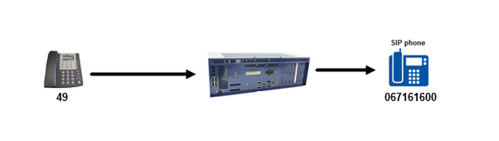
The Abilis has the following CTIR route:
[14:16:33] ABILIS_CPX:d ctir pr:2

Last change: 17/11/2015 15:37:42 CET

---+------+-----------------+---------+--------------------+--------------------
PR |[DESCR]
   |BCI   |POI |SR      |GI |OUT      |CDI                 |CDO
ACT|NEXT        |LAST       |EEC |T301|CGI                 |CGO
EDT|SP    |SC   |DJ   |MJ   |FMDJ|FMMJ|SDI                 |SDO
   |SPOUT |SCOUT|DJOUT|MJOUT|LCS |LCST|SGI                 |SGO
   |                        |BCO      |RGI                 |RGO
   |FMRLY |FAXSP|MODSP|FMLVL|ECM |UDT |IG  |OG  |SG        |DL  |DH
   |CODERS
   |CODERSOUT
   |TI1 .. TI5
--------------------------------------------------------------------------------
2   VOICE  149  #        #   Sip       99                   067161600
    NO           ANY         NO   Dft  *                    067161699
    64000  Sys   Sys   Sys   Sys  Sys  *                    *
--------------------------------------------------------------------------------
Debug Log can be simultaneously sent to the current Control Port session using start ldm or start ldme commands. Events are displayed in the same time that they occurs and that they're recorded into the buffer in memory.
Example of debug log and his explanation:
[14:24:26] ABILIS_CPX:start ldme

Current Local Time: Thursday 19/11/2015 14:35:01 (UTC+1.00)

Start Debug Log content real-time logging (Type CTRL+C + ENTER to stop):

Date   Time   Resource   Ses   Id   Event          Parameters
------ ------ ---------- ----- ---- -------------- --------------------------------------
191115 143556 CtiP-149       8    8 E-DialRx       CH:1 BC:Speech CG:uxq49 USER:21

# The user 21 with number 49 make a call. The call is made from CTIP-149.

191115 143556 CtiP-149       8    8 E-CallRx       CH:1 BC:Speech CD:ux99 CG:uxq49
                                                   USER:21

# The Abilis CTI router receive a call from CTIP-149 (number:49) to number 99.

191115 143556 CtiP-149       8    8 E-Route Match  PR:2

# The Abilis CTI router have matched the priority PR:2  for this incoming call.

191115 143556 CtiSip         8    8 E-CallTx       BC:Speech TY:VtoS CD:ux067161600
                                                   CG:uxq067161699
                                                   CODERS:G.711A,G.711u,Spirit,G.729A

# The Abilis CTI router forward the call to SIP. He change the CD from 99 to 067161600 and CG from 49 to 067161699 and send his list of allowed coders.

191115 143556 CtiP-149       8    8 E-NumComplete  CDI:ux99 CDO:ux067161600
191115 143558 CtiSip         8    8 E-ProgressRx   PI:81 88 USER:sip_unite CODERS:G.711A

# The ABILIS CTISIP forward the call to user:sip_unite.

191115 143558 CtiP-149       8    8 E-ProgressTx   PI:81 88
191115 143559 CtiSip         8    8 E-AlertRx      CH:8 CODERS:G.711A
191115 143559 CtiP-149       8    8 E-AlertTx      CH:1 PI: 81 88

# The Abilis CTISIP confirm the call and send the alerting tone. The selected coders is G.711A.

191115 143602 CtiSip         8    8 E-ConnRx       CH:8 CODERS:G.711A
191115 143602 CtiP-149       8    8 E-ConnTx       CH:1

# The caller answered.

191115 143624 CtiSip         8    8 E-DiscRx       CH:8 CAUSE:80 90 (U, Normal call
                                                   clearing) USER:sip_unite
191115 143624 CtiSip         8    8 E-DiscConfTx   CH:8
191115 143624 CtiP-149       8    8 E-DiscTx       CH:1 CAUSE:80 90 (U, Normal call
                                                   clearing) USER:21

# The caller has closed the call.
In this example the user 21 with the number 49 has made a call to number 99 and the CTIR router has forwarded this call to the number 067161600, and also the CTIR router have changed the calling number from 49 to 067161699. The call has received from CTIP-149 and has sent it to SIP.
| Note |
|---|---|
To view the debug log for the previous calls use the command: d ldme. |
The following command shows the available DSP and their state; it shows the maximum number of possible simultaneous calls.
[08:40:39] ABILIS_CPX:d d ctiac

-------------------------------------------------------------------------------
AC   Card    DSP/C Bus/TS  DSPState ACState  ModeIn  ModeOut Coder      Ctip/BC
-------------------------------------------------------------------------------
  0  BRI4-2    0/0   1/00  RUN      IDLE     -       -       -                -
  1  BRI4-2    0/1   1/01  RUN      IDLE     -       -       -                -
  2  BRI4-2    0/2   1/02  RUN      IDLE     -       -       -                -
  3  BRI4-2    0/3   1/03  RUN      IDLE     -       -       -                -
  4  BRI4-2    1/0   1/05  RUN      IDLE     -       -       -                -
  5  BRI4-2    1/1   1/06  RUN      IDLE     -       -       -                -
  6  BRI4-2    1/2   1/07  RUN      IDLE     -       -       -                -
  7  BRI4-2    1/3   1/08  RUN      IDLE     -       -       -                -
Use the following command to view information in extended format.
[16:16:41] ABILIS_CPX:d de ctiac

-------------------------------------------------------------------------------
AC   Card    DSP/C  Bus/TS DSPState ACState  ModeIn  ModeOut Coder      Ctip/BC
     Dtmf    DhVol  DlVol  FmLevel  InGain   OutGain SigGain MaxFaxSp  MaxModSp
     SC      V-DJ   V-MJ   V-CurJ   V-TopJ   V-AvgJ  EC      BypassCoder
     ECM     FM-DJ  FM-MJ  FM-CurJ  FM-TopJ  FM-AvgJ FaxTxPg FaxFlowState
-------------------------------------------------------------------------------
  0  BRI4-2    0/0    8/00 RUN      IDLE     -       -       -                -
  1  BRI4-2    0/1    8/01 RUN      IDLE     -       -       -                -
  2  BRI4-2    0/2    8/02 RUN      IDLE     -       -       -                -
  3  BRI4-2    0/3    8/03 RUN      IDLE     -       -       -                -
  4  BRI4-2    1/0    9/05 RUN      IN-USE   VOICE   VOICE   Spirit/6.4k 108/01
     OUTBAND -4     -6     -9       0        0       0       9600      7200
     NO      50     150    80       100      68      YES     -
             200    400    0        0        0       0       -
  5  BRI4-2    1/1    9/06 RUN      IDLE     -       -       -                -
  6  BRI4-2    1/2    9/07 RUN      IDLE     -       -       -                -
  7  BRI4-2    1/3    9/08 RUN      IDLE     -       -       -                -
The meaning:
ACAudio channel number.
CardCard type.
DSP/CIndex of audio chip on the card. / Index of audio channel in the chip.
Bus/TSIndex of PCM bus on the card. / Index of PCM timeslot on the bus.
DSPStateDSP chip state:
STARTING - Starting;
RESET - Resetting;
DWL-K - Kernel downloading;
DWL-K-OK - Kernel downloaded;
FAILED-K - Kernel download
failed;
DWL-P - Program downloading;
DWL-P-O - Program downloaded;
FAILED-P - Program download
failed;
INIT - Initializng;
INIT-OK - Initialized;
RUN - Active;
FAILED-R - Failed;
RESET-F - Reset failed;
DISABLED - disabled.
ACStateDSP channel state;
IDLE - Closed;
RESERVED - Open;
IN-USE - Running;
STOPPED - Stopped.
ModeInDSP channel mode based on incoming frames:
VOICE, FAX-T,
FAX, DATA,
SILENCE, BFI,
DTMF, SID.
ModeOutDSP channel mode based on outgoing frames:
VOICE, FAX-T,
FAX, DATA,
SILENCE, BFI,
DTMF, SID.
CoderA set of allowed audio codecs. One bit means one codec type.
Ctip/BCCTI port number currently connected to this audio channel. / B-channel currently connected to this audio channel.
DtmfInband/outband DTMF relay.
DhVolDTMF high freq. level.
DlVolDTMF low freq. level.
FmLevelFax level.
InGainInput audio gain.
OutGainOutput audio gain.
SigGainSignal gain.
MaxFaxSpMaximum bit speed allowed for fax relay transfer.
MaxModSpMaximum bit speed allowed for modem relay transfer.
SCA flag that indicates whether the silence suppression mode is enabled or disabled.
V-DJVoice - default jitter - configured.
V-MJVoice - maximal jitter - configured.
V-CurJVoice - current jitter.
V-TopJVoice - top jitter - compensation delay reached.
V-AvgJVoice - average jitter compensation of call.
ECFlag that indicates whether the Echo canceler is enabled or not.
BypassCoderA set of allowed bypass codecs. One bit means one codec type. Meaning of individual bits is identical to those of AudioCodecs field.
ECMFlag that indicates if Error correction mode is enabled for Fax/Data.
FM-DJFax modem - default jitter - configured.
FM-MJFax modem - maximal jitter - configured.
FM-CurJFax modem - current jitter.
FM-TopJFax modem - top jitter compensation delay reached.
FM-AvgJFax modem - average jitter compensation of call.
FaxTxPgTransmitted pages - meaning only during FAX connection.
FaxFlowStateFlow state of FAX connection. Possible states: Rx-CED, Rx-V.21, Rx-DIS, Tx-DCS, Tx-DTC, Tx-TCF, Rx-preMSG-rsp, Tx-image-MSG, Tx-postMSG-cmd, Rx-postMSG-rsp, Tx-CTC Tx-DCN, Tx-CED, Tx-V.21, Tx-DIS, Rx-DCS, Rx-DTC, Rx-TCF, Tx-preMSG-rsp, Rx-image-MSG, Rx-postMSG-cmd, Tx-postMSG-rs, Rx-CTC Rx-DCN.
Type the following commands to show the statistics about DSP and audio coders:
[08:48:57] ABILIS_CPX:d s ctiac

-------------------------------------------------------------------------------
AC's Statistics were cleared 5 days 20:31:36 ago, on 10/08/2018 at 17:45:06
-------------------------------------------------------------------------------

AC:0   CARD:BRI4-2
       -----------|---INPUT---|--OUTPUT---|-----------|---INPUT---|--OUTPUT---|
       OPEN       |         86|           |CLOSE      |         86|           |
       PCK        |     521791|     446607|CHR        |   20656562|   15657186|
       VOICE-UND  |           |        424|FM-UND     |           |          0|
       VOICE-OVR  |           |        105|FM-OVR     |           |          0|
       VOICE-LOST |          0|           |FM-LOST    |          0|           |
       FRM        |     633056|     446390|FRM-FAX-BYP|          0|          0|
       FRM-VOICE  |     501398|     429708|FRM-FAX-REL|         88|       1291|
       FRM-SILENCE|     120687|      15317|FRM-CED    |          1|          2|
       FRM-SID    |       7502|          0|FRM-FAX-DUM|       3330|           |
       FRM-DTMF   |         50|          0|FAX-TOUT   |          0|           |
       TX-UND     |           |        404|RX-OVR     |          0|           |
       MDC        |          0|           |CMD        |           |       1376|
       ------------------------------------------------------------------------

AC:1   CARD:BRI4-2
       -----------|---INPUT---|--OUTPUT---|-----------|---INPUT---|--OUTPUT---|
       OPEN       |         83|           |CLOSE      |         83|           |
       PCK        |     266191|     222528|CHR        |   16375754|   13084940|
       VOICE-UND  |           |       3117|FM-UND     |           |          0|
       VOICE-OVR  |           |        314|FM-OVR     |           |          0|
       VOICE-LOST |          1|           |FM-LOST    |          0|           |
       FRM        |     339277|     222144|FRM-FAX-BYP|          0|          0|
       FRM-VOICE  |     256918|     209117|FRM-FAX-REL|        630|       5469|
       FRM-SILENCE|      62069|       7497|FRM-CED    |          7|          0|
       FRM-SID    |       3175|          0|FRM-FAX-DUM|      16445|           |
       FRM-DTMF   |         33|          2|FAX-TOUT   |          0|           |
       TX-UND     |           |       2886|RX-OVR     |          1|           |
       MDC        |          0|           |CMD        |           |       1093|
       ------------------------------------------------------------------------

AC:2   CARD:BRI4-2
       -----------|---INPUT---|--OUTPUT---|-----------|---INPUT---|--OUTPUT---|
       OPEN       |         85|           |CLOSE      |         85|           |
       PCK        |     212028|     213795|CHR        |   11544936|   11103158|
       VOICE-UND  |           |        677|FM-UND     |           |          0|
       VOICE-OVR  |           |        341|FM-OVR     |           |          3|
       VOICE-LOST |          2|           |FM-LOST    |          0|           |
       FRM        |     258895|     213321|FRM-FAX-BYP|          0|          0|
       FRM-VOICE  |     205093|     206882|FRM-FAX-REL|        707|       1828|
       FRM-SILENCE|      44488|       4546|FRM-CED    |          2|          4|
       FRM-SID    |       2275|          0|FRM-FAX-DUM|       6324|           |
       FRM-DTMF   |          6|          3|FAX-TOUT   |          0|           |
       TX-UND     |           |        615|RX-OVR     |          0|           |
       MDC        |          0|           |CMD        |           |       1224|
       ------------------------------------------------------------------------

AC:3   CARD:BRI4-2
       -----------|---INPUT---|--OUTPUT---|-----------|---INPUT---|--OUTPUT---|
       OPEN       |         81|           |CLOSE      |         81|           |
       PCK        |     329029|     353294|CHR        |   16531696|   14974230|
       VOICE-UND  |           |       3287|FM-UND     |           |          0|
       VOICE-OVR  |           |       1369|FM-OVR     |           |          0|
       VOICE-LOST |          5|           |FM-LOST    |          0|           |
       FRM        |     414667|     351840|FRM-FAX-BYP|          0|          0|
       FRM-VOICE  |     320074|     340720|FRM-FAX-REL|        176|       1323|
       FRM-SILENCE|      87166|       9734|FRM-CED    |          2|          0|
       FRM-SID    |       3181|          0|FRM-FAX-DUM|       4051|           |
       FRM-DTMF   |         17|          0|FAX-TOUT   |          0|           |
       TX-UND     |           |       2904|RX-OVR     |          0|           |
       MDC        |          0|           |CMD        |           |       1361|
       ------------------------------------------------------------------------

AC:4   CARD:BRI4-2
       -----------|---INPUT---|--OUTPUT---|-----------|---INPUT---|--OUTPUT---|
       OPEN       |         84|           |CLOSE      |         84|           |
       PCK        |     424578|     388329|CHR        |   37589920|   34629560|
       VOICE-UND  |           |        663|FM-UND     |           |          0|
       VOICE-OVR  |           |        566|FM-OVR     |           |          3|
       VOICE-LOST |          0|           |FM-LOST    |          0|           |
       FRM        |     479323|     387648|FRM-FAX-BYP|          0|          0|
       FRM-VOICE  |     414983|     381352|FRM-FAX-REL|        983|         88|
       FRM-SILENCE|      57939|       6141|FRM-CED    |          0|          4|
       FRM-SID    |       3063|          0|FRM-FAX-DUM|       2292|           |
       FRM-DTMF   |         63|          0|FAX-TOUT   |          0|           |
       TX-UND     |           |        629|RX-OVR     |          0|           |
       MDC        |          0|           |CMD        |           |       1271|
       ------------------------------------------------------------------------

AC:5   CARD:BRI4-2
       -----------|---INPUT---|--OUTPUT---|-----------|---INPUT---|--OUTPUT---|
       OPEN       |         84|           |CLOSE      |         84|           |
       PCK        |     600272|     497017|CHR        |   26027434|   19455056|
       VOICE-UND  |           |        579|FM-UND     |           |          0|
       VOICE-OVR  |           |        119|FM-OVR     |           |          0|
       VOICE-LOST |          0|           |FM-LOST    |          0|           |
       FRM        |     734820|     496826|FRM-FAX-BYP|          0|          0|
       FRM-VOICE  |     576501|     481701|FRM-FAX-REL|        126|       1948|
       FRM-SILENCE|     144277|      13088|FRM-CED    |          2|          2|
       FRM-SID    |       8851|          0|FRM-FAX-DUM|       5061|           |
       FRM-DTMF   |          2|         34|FAX-TOUT   |          0|           |
       TX-UND     |           |        249|RX-OVR     |          0|           |
       MDC        |          0|           |CMD        |           |       1153|
       ------------------------------------------------------------------------

AC:6   CARD:BRI4-2
       -----------|---INPUT---|--OUTPUT---|-----------|---INPUT---|--OUTPUT---|
       OPEN       |         84|           |CLOSE      |         84|           |
       PCK        |     374751|     373547|CHR        |   18749814|   16331086|
       VOICE-UND  |           |       1775|FM-UND     |           |          0|
       VOICE-OVR  |           |        904|FM-OVR     |           |          2|
       VOICE-LOST |          3|           |FM-LOST    |          0|           |
       FRM        |     488459|     372587|FRM-FAX-BYP|          0|          0|
       FRM-VOICE  |     357758|     355873|FRM-FAX-REL|       1495|       2515|
       FRM-SILENCE|     113082|      14123|FRM-CED    |          4|          2|
       FRM-SID    |       5827|          0|FRM-FAX-DUM|      10236|           |
       FRM-DTMF   |         57|         11|FAX-TOUT   |          0|           |
       TX-UND     |           |       1517|RX-OVR     |          1|           |
       MDC        |          0|           |CMD        |           |       1229|
       ------------------------------------------------------------------------

AC:7   CARD:BRI4-2
       -----------|---INPUT---|--OUTPUT---|-----------|---INPUT---|--OUTPUT---|
       OPEN       |         81|           |CLOSE      |         81|           |
       PCK        |     444140|     354474|CHR        |   19114900|   14292406|
       VOICE-UND  |           |       1133|FM-UND     |           |          0|
       VOICE-OVR  |           |        438|FM-OVR     |           |          0|
       VOICE-LOST |          5|           |FM-LOST    |          0|           |
       FRM        |     563101|     353994|FRM-FAX-BYP|          0|          0|
       FRM-VOICE  |     428131|     340864|FRM-FAX-REL|        328|       2156|
       FRM-SILENCE|     122093|      10900|FRM-CED    |          4|          0|
       FRM-SID    |       5856|          0|FRM-FAX-DUM|       6635|           |
       FRM-DTMF   |         54|         18|FAX-TOUT   |          0|           |
       TX-UND     |           |        925|RX-OVR     |          0|           |
       MDC        |          0|           |CMD        |           |       1180|
       ------------------------------------------------------------------------
With reference to the shown interval of time («cleared 5 days 20:31:36 ago») these counters show the number of:
AC | Audio channel number. |
CARD | Card type and index. |
OPEN | Number of channel opening. |
CLOSE | Number of channel closing. |
PCK | NCBs for read from/write to DSP channel from upper layer. |
CHR | Rx/Tx bytes from/to DSP chip |
VOICE-UND | Number of out underruns. |
FM-UND | Number of out fax modem underruns. |
VOICE-OVR | Number of out overruns. |
VFM-OVR | Number of out fax modem overruns. |
VOICE-LOST | Lost voice frames on Rx side. |
FM-LOST | Lost fax modem frames on Rx side. |
FRM | Rx/Tx frames from/to DSP chip. |
FRM-VOICE | Rx/Tx voice frames. |
FRM-SILENCE | Silence frames. |
FRM-SID | SID frames. |
FRM-DTMF | DTMF frames. |
FRM-FAX-BYP | Fax bypass frames. |
FRM-FAX-REL | Fax relay frames. |
FRM-CED | CED frames. |
FRM-FAX-DUM | Dummy (FAX or DATA) messages from DSP channel. |
FAX-TOUT | Dummy frames with set TO bit. |
TX-UND | AC DSP "UR" events. |
RX-OVR | Receive Over-run in DSP chip - "ROR" events. |
MDC | Misalignment Detection and Correction. |
CMD | Tx commands. |
The following command shows the available coders supported by CTI cards installed and the number of simultaneous calls.
[08:44:19] ABILIS_CPX:d d ctisys

RES:CtiSys --------------------------------------------------------------------
       CTI_System_general_properties
       CTIR-STATE:ENABLED     CALLS-CURRENT:1      CALLS-PEAK:8
       AC-STATE:ENABLED       AC-CURRENT:1         AC-PEAK:7
       ------------------------------------------------------------------------
       -- Number of simultaneous calls ----------------------------------------
                      | State: Alerting/Connected |        State: Any         |
       ---------------|---Current---|----Peak-----|---Current---|----Peak-----|
       TR             |           0 |           1 |           0 |           1 |
       DATA           |           0 |           1 |           0 |           1 |
       VtoCISDA       |           1 |           5 |           1 |           5 |
       CISDAtoCISDA   |           0 |           2 |           0 |           4 |
       CISDAtoV       |           0 |           2 |           0 |           2 |
       ALL            |           1 |           8 |           1 |           8 |
       ------------------------------------------------------------------------
       - AC and SWAC common available coders ----------------------------------
       -- Coder ---|-- Bit rates (kbps) --|-- Coder ---|-- Bit rates (kbps) --|
       G.711A      |64                    |G.711u      |64                    |
       G.729A      |8                     |TRANSPARENT |64                    |
       Spirit      |6.4, 7.2, 8, 8.8, 9.6 |
       ------------------------------------------------------------------------
       - SWAC and MCD limits by CPU -------------------------------------------
       MAX-SWAC-0ms:28   MAX-SWAC-8ms:24   MAX-SWAC-16ms:22   MAX-SWAC-32ms:19
       MAX-MCD-SPIRIT:28                   MAX-MCD-G729A:33
       - SWAC and MCD diagnostics ---------------------------------------------
       CUR-SWAC:1   PEAK-SWAC:6   REST-SWAC:7   MAX-SWAC:8    LIMIT-SWAC:HDLC
       CUR-MCD:0    PEAK-MCD:2                  MAX-HDLC:8
       ------------------------------------------------------------------------
       - Clock Sources for H100 cards -----------------------------------------
       CLK:38
       - Clock Sources for NOT-H100 cards -------------------------------------
                          *** No NOT-H100 cards running ***
The meaning:
CTIR-STATECTI routing state.
CALLS-CURRENTCurrent number of simultaneous calls in any state.
CALLS-PEAKPeak number of simultaneous calls in any state.
AC-STATEAudio Codec state.
AC-CURRENTCurrent number of AC.
AC-PEAKPeak number of used AC.
MAX-SWAC-0msNumber of SWAC permitted by CPU with 0 ms echo tail.
MAX-SWAC-8msNumber of SWAC permitted by CPU with 8 ms echo tail.
MAX-SWAC-16msNumber of SWAC permitted by CPU with 16 ms echo tail.
MAX-SWAC-32msNumber of SWAC permitted by CPU with 32 ms echo tail.
MAX-MCD-SPIRITMaximal number of MCD for the 'SPIRIT' codec permitted by CPU.
MAX-MCD-G729AMaximal number of MCD for the 'G729A' codec permitted by CPU.
CUR-SWACCurrent number of swac channels.
PEAK-SWACPeak number of swac channels.
REST-SWACRemaining number of swac channels considering current ec-tail, cpu limit, cfg limit.
MAX-SWACMaximal number of swac channels considering current ec-tail, cpu limit, cfg limit.
LIMIT-SWACThe reason of the limit: CFG,
CPU, HDLC.
CUR-MCDCurrent number of MCD.
PEAK-MCDPeak number of MCD.
MAX-HDLCMaximal number of HDLC channels that support SWAC.
CLKPort actually used for clock recovery.
This command can help to understand what is happening, in case of troubles:
[08:49:51] ABILIS_CPX:d s ctisys

RES:CtiSys --------------------------------------------------------------------
       CTI_System_general_properties
      --- Cleared 5 days 22:40:27 ago, on 10/08/2018 at 17:45:06 -------------
      -- Number of successful (connected) calls, updated at call end ----------
      ------------|---INPUT---|--OUTPUT---|--LOCAL----|--TRANSIT--|----SUM----|
      TR          |          0|          6|          9|          0|         15|
      DATA        |          2|          0|          0|           |          2|
      VtoCISDA    |          0|         33|          0|         16|         49|
      CISDAtoCISDA|          1|          0|          0|         30|         31|
      CISDAtoV    |         21|          0|          0|          2|         23|
      SUM         |         24|         39|          9|         48|        120|
      -------------------------------------------------------------------------
      -- Seconds of successful (connected) calls, updated at call end ---------
      ------------|---INPUT---|--OUTPUT---|--LOCAL----|--TRANSIT--|----SUM----|
      TR          |          0|        610|        422|          0|       1032|
      DATA        |         72|          0|          0|           |         72|
      VtoCISDA    |          0|       8226|          0|        870|       9096|
      CISDAtoCISDA|         47|          0|          0|       3500|       3547|
      CISDAtoV    |       6773|          0|          0|        473|       7246|
      SUM         |       6892|       8836|        422|       4843|      20993|
      -------------------------------------------------------------------------
      -- Number of unsuccessful calls -----------------------------------------
      ------------|---INPUT---|--OUTPUT---|--LOCAL----|--TRANSIT--|----SUM----|
      TR          |          0|          3|          3|          0|          6|
      DATA        |          0|          0|          0|           |          0|
      VtoCISDA    |          0|         32|          0|          0|         32|
      CISDAtoCISDA|          0|          0|          0|          4|          4|
      CISDAtoV    |         12|          0|          0|          2|         14|
      SUM         |         12|         35|          3|          6|         56|
      -------------------------------------------------------------------------
      -- Internal failures for not connected calls ----------------------------
      ------------|---INPUT---|--OUTPUT---|--LOCAL----|--TRANSIT--|----SUM----|
      NoRoute     |           |           |           |           |          0|
      NoDest      |           |           |           |           |          0|
      No-C-CISDA  |           |           |           |           |          0|
      NoPcmRes    |          0|          0|          0|          0|          0|
      NoAcRes     |          0|          0|          0|          0|          0|
      NoEecRes    |          0|          0|          0|          0|          0|
      NoHdlcRes   |          0|          0|          0|           |          0|
      NoAcCodec   |          0|          0|          0|          0|          0|
      PlinkFail   |          0|          0|           |          0|          0|
      BwLimit     |           |          0|           |          0|          0|
      IsdnL1down  |          0|          0|          0|          0|          0|
      IsdnL2down  |          0|          0|          0|          0|          0|
      -------------------------------------------------------------------------
      -- Internal failures after call connected -------------------------------
      ------------|---INPUT---|--OUTPUT---|--LOCAL----|--TRANSIT--|----SUM----|
      PlinkFail   |          0|          0|           |          0|          0|
      IsdnL1down  |          0|          0|          0|          0|          0|
      IsdnL2down  |          0|          0|          0|          0|          0|
      -------------------------------------------------------------------------
With reference to the shown interval of time («Cleared 5 days 22:40:27 ago») these counters show the number of:
NoRoute | Numbers of internal failures with "No route to destination". |
NoDest | Numbers of internal failures with "Incompatible destination.". |
No-C-CISDA | It is increased when call is refused when the call
exceeds the value configured for
max-c-tofrom-cisda. |
NoAcRes | Numbers of internal failures with "No AC available". |
NoEecRes | Numbers of internal failures with "No EEC available". |
NoHdlcRes | Numbers of internal failures with "No HDLC available.". |
NoAcCodec | Numbers of internal failures with "No AC available". |
BwLimit | Numbers of internal failures with "Not enough bandwidth". |
IsdnL1down | Numbers of internal failures with "Destination out of order (NRC_L1DOWN). Level 1 of the ISDN is inactive". |
IsdnL2down | Numbers of internal failures with "Destination out of order (NRC_L2DOWN). Level 2 of the ISDN is inactive, or failed to activate". |
| |  | |
| 56.9. CPO - Call path optimization |  | 56.11. Examples of CTI configuration |