| 2.10. USB devices | ||
|---|---|---|
 | Chapter 2. Abilis hardware |  |
| 2.10. USB devices | ||
|---|---|---|
| | Chapter 2. Abilis hardware | |
The ADSL USB modem enables one or more ADSL connections (one for each modem) directly on the Abilis without installing any additional router. Up to 6 modems can be installed into the same Abilis.
Actually three models are supported:
Abilis-5800UB (Supported from 7.0.6 and from 6.5.13);
Aethra Starmodem which uses the USB isochronous mode for the downstream. (Supported from 7.0.3 and from 6.5.11);
Thomson Speedtouch.
![[Warning]](../images/warning.png) | Warning |
|---|---|
The number of ADSL StarModem which can be connected to the same USB 1.1 OHCI/UHCI controller is limited. Refer to Section 2.10.1.3, “Isochronous mode” to havo more information about isochronous mode. |
![[Tip]](../images/tip.png) | Tip |
|---|---|
Interesting chapters: Section 3.5, “ADSL modem connection”; Section 64.4, “How to configure ADSL connections using USB modems”. |
| Led | Meaning | State |
|---|---|---|
| Power | Power state. | OFF: USB calbe disconnected. ON: USB calbe connected. |
| ADSL | ADSL state. | OFF or blinking GREEN: device not able to synchronize. ON: adsl connection established |
| Data | Data exchange. | Blinking: during data exchange. |
| Led | Meaning | State |
|---|---|---|
Power DSL | Power state. DSL State. | Both leds OFF: modem disconnected. Power led is RED or blinking AMBER: device not working properly. Power led is GREEN and DSL led is OFF or blinking GREEN: device not able to synchronize. |
WARNINGS about isochronous mode:
USB 1.1 interfaces are handled with one OHCI/UHCI controller every 2 ports. Usually the ports that are close each other belongs to the same UHCI/OHCI controller;
USB 2.0 interfaces are handled with one EHCI controller for all the ports. In some rare cases, or when a PCI add on card is used, more EHCI controllers can be present;
isochronous mode reserves bandwidth on each USB controller. This means that the bandwidth is permanently robbed to other devices connected to the same controller;
the maximal theoretical USB bandwidth on USB 1.1. FULL SPEED is 12 Mbit/sec;
the maximal theoretical USB bandwidth on USB 2.0. HIGH SPEED is 480 Mbit/sec;
some bandwidth must be left free for interrupt and bulk transaction;
in Abilis CPX the maximal isochronous bandwidth limit for USB 1.1 is 9.6 Mbit/sec;
in Abilis CPX the maximal isochronous bandwidth limit for USB 2.0 is 384 Mbit/sec;
in Abilis CPX the isochronous bandwidth is dynamically reserved depending on the actual downstream (RX) speed, in 8 discrete step which are roughly 1,2,3,4,5,6,7,8 Mbit/sec.
As a result there is a limitation to the number of ADSL StarModem which you can connect to the same USB 1.1 OHCI/UHCI controller, as well as combination of StarModem with GSM-BOX and UMTS-BOX/BOX2, for example:
one StarModem at maximal speed and one UMTS-BOX/BOX2 are supported within a OHCI/UHCI controller;
two StarModem connected to 4 mbit/sec lines and one UMTS-BOX/BOX2 are also supported.
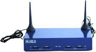
UMTS-BOX2 is a device which provides two independent interfaces to the GSM/UMTS mobile network. It can be connected to ABILIS router through an USB cable and supports full Voice, Data and SMS service.
Generally UMTS-BOX2 works with a SIM inserted in it, but using the sim remotization the device can use a sim located anywhere in the world.
The most important benefits of sim remotization are:
centralization of the SIM when a number of UMTS-BOX2 are dispersed in branch offices;
the management of sims is very malleable because the association between SIM and UMTS-BOX2 can be changed using software commands;
the association between SIM and UMTS-BOX2 can be changed by external applications that follow arbitrary customer rules.
The following steps are executed when connecting umtsbox2:
UMTS-BOX2 gets connected to abilis after 15 seconds when UMTS-BOX2/Abilis boots;
once UMTS-BOX2 gets connected, the communication with Abilis starts after 5 seconds;
If Abilis doesn't drive UMTS-BOX2, UMTS-BOX2 waits 40 seconds and then resets itself. After the reset, the procedure starts from point #1.
If Abilis drives UMTS-BOX2 and the sim-container is inside the module and a sim isn't in the container, the module resets itself. If the sim is remote this doesn't happen;
a module resets itself every time a remote sim is connected. If the UMTS-BOX2 is connected to a UHCI controller, the reset can cause the disconnection of the other module. Sim-remotization must not be used when UMTS-BOX2 is connected to an UCHI controller.
| Tip |
|---|---|
Interesting chapters: |
| Led | Meaning | State |
|---|---|---|
| Act(Module1/Module2) | Umts module activity. | OFF: module off or inactive. ON: module ON, not registered with the network or communicating. ON FLASHING: module ON, registered with the network but inactive |
| SIM 1a/1b/2a/2b | Presence of sims inside 1a/1b/2a/2b slots | ON: sim inserted while UMTS module is reading the sim. OFF: not inserted sim or not selected sim or SIm remotization active NOTE: the led is OFF even if the sim is inserted and the UMTS module is not reading the sim |
PWR USB | Power state USB state | PWR OFF and USB OFF: power cable may be correctly connected but it doesn't matter; USB disconnected. PWR OFF and USB ON: power disconnected or usb not driven by software; USB connected. POWER ON and USB ON: power correctly connected; USB connected and driven by software. NOTE: if USB cable is disconnected, PWR led is always OFF even if the power cable is correctly connected. |
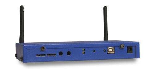
Dimensions: 234x163x45;
Weight: 1.20Kg;
Power is provided both via USB to HUB, CODEC and PIC and with the additional power cable to SimCom modules. SimCom modules absorpt some current from the USB anyway, because of an internal -USB-powered- USB-to-serial converter interface chip.
Table 2.19. Power consumption on the USB
| Device status | Supply voltage (V) | Consumed current (mA) |
|---|---|---|
| USB connected, modules powered down | 5 | 185 |
| USB connected, module1 powered up | 5 | 285 |
| USB connected, module1 and module2 powered up | 5 | 385 |
Table 2.20. Power consumption on the Power supply cable
| Device status | Supply voltage (V) | Consumed current (mA) |
|---|---|---|
| Modules in power down | 5/12 | 100/50 |
| Both modules in stanbdy | 5/12 | 250/100 |
| Both modules during a phone call | 5/12 | 650/300 |
| Both modules during HSDPA download, 23dB power (max power) | 5/12 | 1900/640 |
The GSM Box is an add-on for the ABILIS CPX which provides an interface between the GSM and the fixed (private/public) telephone network.
Thanks to the Abilis GSM Box mobile phones can be considered as “mobile extensions” of the company's telephone system. Additionally, the Abilis “Least Cost Router” permits to select the cheapest route for any call.
The GSM Box is connected to the Abilis by means of an USB interface (see Section 3.7, “UMTS-BOX connection”), thus requiring no additional telecom port in the ABILIS router and preservinging digital voice quality.
The main features of the GSM Box are:
two simultaneous channels;
works even without SIM cards;
high-fidelity voice;
call-back;
unlimited Least Cost Routing (LCR);
DTMF dial-in with voice message;
call data records;
SMS to e-mail;
SMA connector with SMA detachable antennas.
There are two versions of GSM Box:
One channel device (doesn't require an external power supply.Power is supplied by usb cable);
two channels device (require an external 5V-DC power supply).
| Tip |
|---|---|
Interesting chapters: Chapter 11, GSM-UMTS BOX. |
Led indications for a two channels device:
| Led | Meaning | State |
|---|---|---|
| POWER | Power state. | OFF: the 5V-DC are not provided. ON: the 5V-DC are provided. |
| USB active | USB state. | OFF: USB connection not available. ON: USB connection available. |
Channel 1 Channel 2 | GSM module state | OFF:module powered down. Blinks 0.6 s ON and 0.6 s OFF: module powered up, loading from SIM card or registering to the network. Blinks 0.2 s ON and 3 s OFF: module registered to the network and idle. ON: GSM activity (a phone call, internet traffic) |
Led indications for a one channel device:
| Led | Meaning | State |
|---|---|---|
| POWER | Power state. | OFF: the 5V-DC are not provided. ON: the 5V-DC are provided. |
| USB active | USB state. | OFF: USB connection not available. ON: USB connection available. |
Channel 1 | GSM module state | OFF:module powered down. Blinks 0.6 s ON and 0.6 s OFF: module powered up, loading from SIM card or registering to the network. Blinks 0.2 s ON and 3 s OFF: module registered to the network and idle. ON: GSM activity (a phone call, internet traffic) |
| Channel 2 | GSM module state | NOTE: it's always OFF |
This device allows to exchange data and sms using an UMTS key. It can be used as backup line when the main one fails, or to establish a connection toward Internet when calling an ISDN number (data call back).
Citobox allows to connect Abilis to a doorphone system integrating it with your computer telephony system.
It provides 8 digital inputs and 4 digital outputs which can be used to drive other hardware (to open a gate, to switch on lights, etc.).
A Citobox allows to:
connect one outdoor system and one indoor system, or two outdoor systems;
get a call when person at the door presses the ring button;
![[Note]](../images/note.png) | Note |
|---|---|
The communication is cut off when the called party hangs up or when the interface timer expires. This timer is not programmable and its default value is 10 minutes. |
order the door opening by pressing a key that produces DTMF on your phone;
use the inputs for up to 8 additional ring buttons. Each input will cause to dial a different number;
view the state of inputs/output through the GPIO module, which allows interfacing with an external application through HTTP/XML.
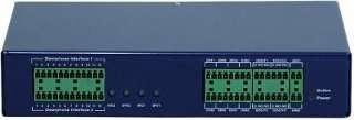
On the front there are:
2 interfaces (each interface can be used to connect a doorphone system (indoor + outdoor, outdoor + outdoor, indoor + indoor);
8 digital inputs;
4 digital output (normally open and normally closed relays);
2 analog inputs (each analog input can be configured by installing an analog adaptation module inside the CITOBOX. When no module is present, the analog inputs are not usable).
The device can accept both 5V and 12V power supply.
| Tip |
|---|---|
Interesting chapters: |
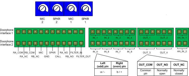
The front panel contains the trimmers for the volume regulation, the doorphone interface connectors and the I/O connectors.
The trimmers allow to regulate the volume of the microphone and the speaker (clockwise: rise the volume, counterclockwise: lower the volume).
The following picture shows the trimmers and the connector pinout.
Each doorphone interface contains two relays, RA and RB, whose "normally close" pins are closed and "normally open" pins are open when there is no active communication on the interface (default state).
Table 2.21. Citobox pinout
| Pin number | Pin name | Description | Direction |
|---|---|---|---|
| 1 | RA_COM | RA relay, common pin | Clean contact |
| 2 | RA_NC | RA relay; when the communication on the corresponding Doorphone interface is inactive, this pin is short-circuited with RA_COM; when the communication is active, this pin is not connected | Clean contact |
| 3 | RB_COM | RB relay, common pin | Clean contact |
| 4 | RB_NC | RB relay; when the communication on the corresponding Doorphone interface is inactive, this pin is short-circuited with RB_COM; when the communication is active, this pin is not connected | Clean contact |
| 5 | MIC | Microphone input; connect to the doorphone's microphone | Input |
| 6 | GND | Ground reference | - |
| 7 | SPKR | Speaker output; connect to the doorphone's speaker | Output |
| 8 | CALL | CALL button; any DC or AC signal, in the range 2.5-to-12.5 V on this input triggers a CALL event on the corresponding Doorphone interface | Input |
| 9 | RA_NO | RA relay; when the communication on the corresponding Doorphone interface is inactive, this pin is not connected; when the communication is active, this pin is short-circuited with RA_COM | Clean contact |
| 10 | RB_NO | RB relay; when the communication on the corresponding Doorphone interface is inactive, this pin is not connected; when the communication is active, this pin is short-circuited with RB_COM | Clean contact |
| 11 | FILTER_IN | Auxiliary pin, leave disconnected if unused (connect to 12 V DC in a special BTicino connection scheme in order to provide power to the Microphone line) | - |
| 12 | FILTER_OUT | Auxiliary pin, leave disconnected if unused (connect to MIC in a special BTicino connection scheme, in order to provide power to the Microphone line) | - |
The digital inputs are general purpose, so they can be used to connect any kind of hardware (additional ring buttons, digital sensors, etc.). Refer to Section 13.3, “CTI port configuration” to have more information about their configuration.
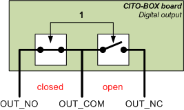
The digital outputs can drive any kind of device, accordingly with the electrical specifications.
The digital outputs are relay-based and have 3 volt free contacts (i.e. dry contacts, i.e. clean contacts): common, normally open and normally closed.
The OUT_NO is the normally open pin. When the DIG_OUT is set to 0, OUT_COM and OUT_NO are disconnected, while when DIG_OUT is set to 1 they are short-circuited.
The OUT_NC is the normally closed pin. When the DIG_OUT is set to 0, OUT_COM and OUT_NC are short-circuited, while when DIG_OUT is set to 1 they are disconnected.
Table 2.23. Digital output pinout
| Pin | Description |
|---|---|
| OUT_COM | Common pin |
| OUT_NO | Normally opened digital out |
| OUT_NC | Normally closed digital out |
| Led | Meaning | State |
|---|---|---|
| Power | Power state. | OFF: external power supply disconnected or faulty. ON: external power supply is connected. |
| Active | USB state. | OFF: USB cable disconnected. Blinks fast (0.5 s ON, 0.5 s OFF): Abilis is not driving the device. Blinks slowly (3 s ON, 3 s OFF): Abilis software is correctly driving the device. |
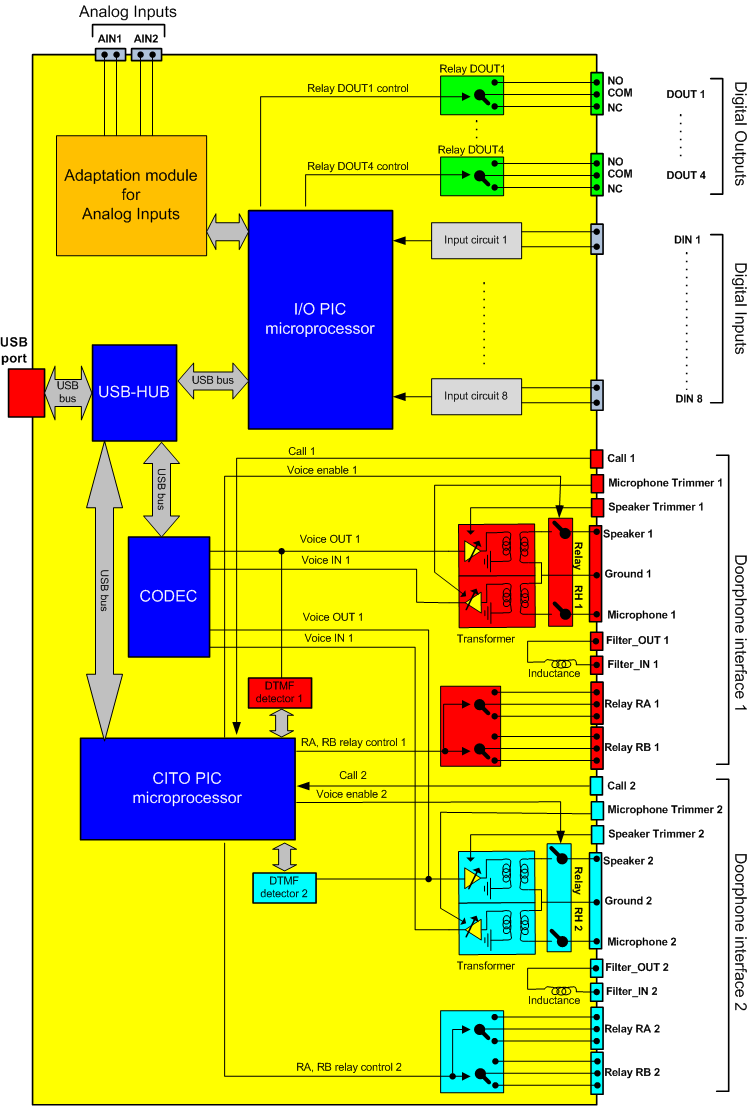
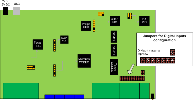
The CITO-BOX is composed by two parts: the CITO part and the IO part. They are managed by two separated PIC microcontrollers: the CITO-PIC and the IO-PIC.
The CITO part offers two completely separated interfaces for doorphones. The IO part offers 8 digital inputs, 4 digital outputs (clean contacts) and two analog inputs (available only if an analog adaptation module is present).
Each interface of the CITO part is mainly composed of 4 analog pins: SPKR, MIC, GND, CALL, which must be connected respectively to the speaker, microphone, ground and call button signals of the doorphone.
When a continuous or alternate voltage (voltange range 2.5V - 12V, frequency range: 0Hz - 100Hz) is applied to the CALL pin, the CITOBOX informs the Abilis, which activates the voice communication on the corresponding interface. The status of the relays RA and RB follows the one of the communication. RA_NC and RB_NC are closed when the communication is inactive and open when the communication is inactive, being the status of no communication the "normal" status. RA_NO and RB_NO follow the opposite behaviour.
The volume of the microphone and the speaker can be manually regulated with the corresponding trimmers, all of which are externally accessible on the front. The speaker and the microphone are decoupled by a transformer.
Each digital output of the IO part is a volt free contact (clean contact) and can be driven separately by the Abilis. Each output is available both as normally closed and normally open. It supports a maximum switching current of 1 A (transition current during the relay closure), a maximum carrying current of 2 A (after the relay closure, when the relay is stable), 220V DC max. voltage and 250V AC max. voltage.
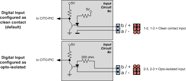
Each input of the IO part is separated. It can be configured as clean contact input (default) or optoisolated input (use voltages in the range 5V - 12V). Each input can be manually configured through its corresponding couple of jumpers.
Jumpers configuration allows to choose between clean contact and opto-isolated digital inputs. Jumpers configuration is available only in PCB Ver. 1.1.The PCB version is reported on the case label. PCB version 1.0 does not allow the configuration of digital inputs. Its digital inputs are only compatible with volt free outputs (clean contacts).

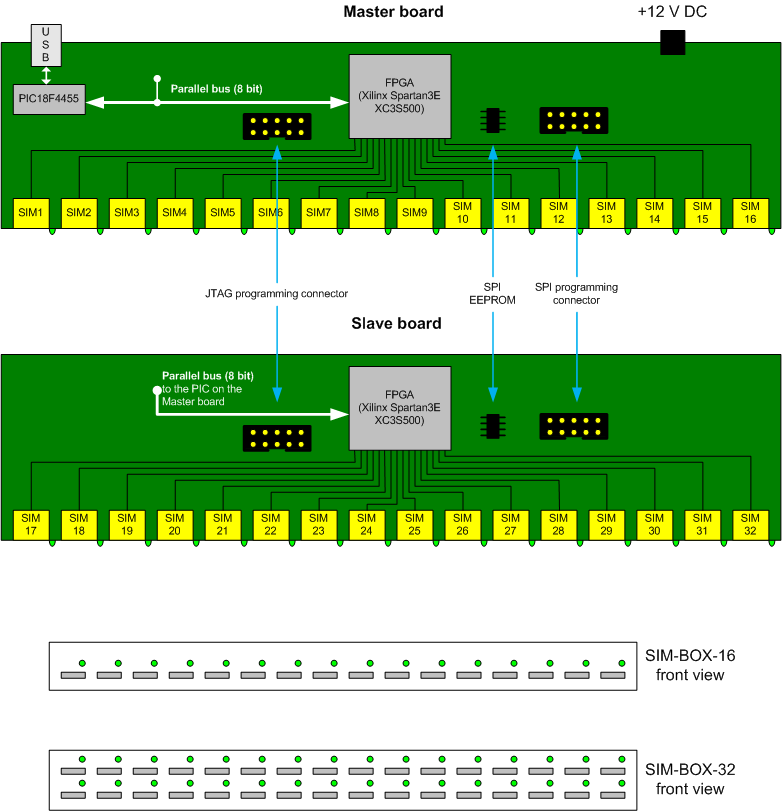
Simbox is a device providing an USB interface to 16 or 32 SIM phone cards.
The potential of this device significantly increases if used with UMTS-BOX2 because of sim remotization.
Sim remotization allows to use remote sim cards inserted in a Simbox with an UMTS BOX2 via IP network.
| Note |
|---|---|
Simbox is not equipped with any GSM/UMTS modem, so it cannot replace an UMTSBOX. Simbox works togheter with one or more UMTSBOXes. |
There are two versions of Simbox:
with 16 sockets for GSM/UMTS sims
with 32 sockets for GSM/UMTS sims.
| Tip |
|---|---|
Interesting chapters: |
| Led | Meaning | State |
|---|---|---|
| Power | Power state. | OFF: external power supply disconnected or faulty. ON: external power supply is connected. |
| SIM #nn | SIM #nn state. | OFF: SIM #nn card not used by the Abilis, even if the SIM card is inserted. ON: SIM #nn card used by the Abilis. |
The SIMBOX-32 is composed of two boards: the master board and the slave board. the SIMBOX-16 is composed of the master board. Each board allows to plug up to 16 sim cards.
Communication between FPGA and PIC is implemented on the PIC's Streaming Parallel Port (SPP) peripheral. This port provides a fast 8-bit bus, where it is possible to connect more slave peripherals.
| Tip |
|---|---|
Interesting chapters: |
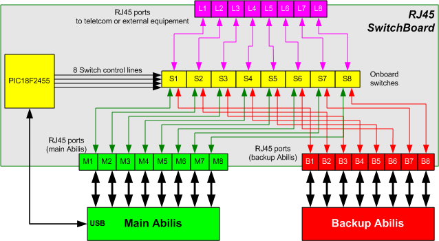
RJS is an ISDN, ADSL or ethernet switch. It's equipped with:
one USB port
8 ports (each port includes 3 ISDN/ethernet ports)
This device checks the keepalive, so if the master (Mx) doesn't reply to the keepalive signal, the link is assumed to be down and the line is switched to the backup device (Bx) until the link is up again.
RJS can handle up to 8 lines.
| Note |
|---|---|
Only the central pins 4,5 and 3,6 are switched! Pins 1,2 and 7,8 are not connected. Refer to chapter Section 3.10.1, “Connection examples” to have more information about connection. |
There are two versions of RJS:
accepting only 5V power supply;
| Warning |
|---|---|
Connecting a power supply providing more than 5V-DC damages the device! |
accepting 12V power supply
| Tip |
|---|---|
Interesting chapters: |
| Led | Meaning | State |
|---|---|---|
| Power | Power state. | OFF: external power supply disconnected or faulty. ON: external power supply is connected. |
| Active | Device state. | Blinks fast (0.5 s ON, 0.5 s OFF): Abilis is not driving the device. Blinks slowly (3 s ON, 3 s OFF): Abilis software is correctly driving the device. |
The RJ Switch is equipped with a PIC microcontroller which controls 8 onboard switches using the control lines. It is installed on the board and it's able to switch each LINE port to the correspondent main port or backup port.
This board contains a watchdog which must be driven by the main Abilis via USB; when the main Abilis stops sending LIVE signals to the board, the PIC understands that the main Abilis is failing and switches the line to the backup Abilis. The board's switch core/watchdog is based on a Microchip PIC18F2450.
| Tip |
|---|---|
Interesting chapters: |
| |  | |
| 2.9. Abilis PCI boards and extension boards |  | Chapter 3. Physical connections |