| 14.1. Analog and digital I/O Overview | ||
|---|---|---|
 | Chapter 14. IOBOX |  |
| 14.1. Analog and digital I/O Overview | ||
|---|---|---|
| | Chapter 14. IOBOX | |
From release 7-5-0 added a new web application that permits the handling of analog and digital I/O made available with the following hardware:
MFIO embedded in Microabilis-C3;
IOBOX.
From release 8-4-0 added new hardware:
The application permits:
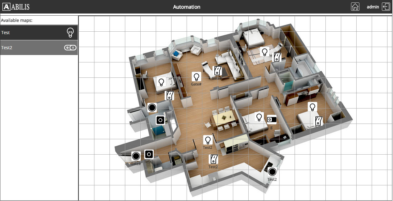
Use of .jpg, .png, .gif, .bmp images as background.
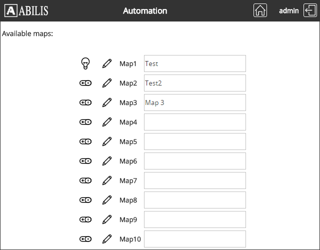
A visual creation of maps (up to 10) and the placement on the map of indicators and actuators.
Drive toggle or pulse output just by clicking on the icon.
"By user" access rights to the maps, and different rights for design and for control.
/sys/io: main page;
/sys/io/control/map<X>: control
maps, where <X> is the map number between 1 and 10;
/sys/io/design/map<X>: design
maps, where <X> is the map number between 1 and 10.
/sys/io/iolog: Automation log.
Real-time indication of states and values of the monitored I/O.
Configurable labels.
Javascript required (recent version of Firefox, Chrome, Safari, Opera, IE 7/8/9).
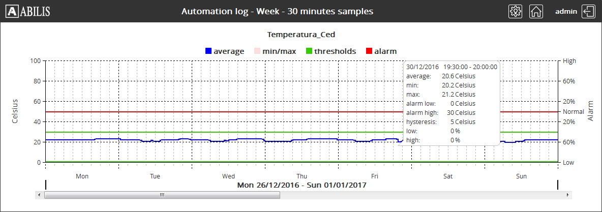
IOLOG events viewable as graphs.
See below a couple of example screenshots.
GPIO/RIO/RVS device
Handling of Analog Inputs values (Only for GPIO and RIO).
Analog signals are digitized by ADC converters present in the interface hardware. The numerical value is read by Abilis and converted to the measure unit by means of the analog input configuration parameters:
UNITUnit of subsequent values. Empty or from 1 up to 8 characters (e.g. kWh, J, Volts, m, km, miles, myunit). Case is preserved.
MINValue corresponding lowest ADC value. It must be < MAX. String representing a floating point number from -9999 to +9999. From 1 up to 6 characters in ['+', '-', '0'..'9', '.'].
MAXValue corresponding to the highest ADC value. It must be > MIN. String representing a floating point number from -9999 to +9999. From 1 up to 6 characters in ['+', '-', '0'..'9', '.'].
UPDValue corresponding to the highest ADC value. It must be > MIN. String representing a floating point number from -9999 to +9999. From 1 up to 6 characters in ['+', '-', '0'..'9', '.'].
POOLPolling period [0.1..300.0 sec].
Handling of Analog Inputs alarms (Only for GPIO and RIO).
The measured analog values are verified against thresholds in order to generate LOW and HIGH alarms.
Analog alarms parameters:
ALM-LOLow threshold for alarm. It must be <
ALM-HI. String representing a floating
point number from -9998 to +9998 or an empty string to disable
it. From 1 up to 6 characters in ['+', '-', '0'..'9',
'.'].
ALM-HIHigh threshold for alarm. It must be >
ALM-LO. String representing a floating
point number from -9998 to +9998 or an empty string to disable
it. From 1 up to 6 characters in ['+', '-', '0'..'9',
'.'].
HYSTHysteresis for ALM-LO and
ALM-HI for returning to NORMAL state.
String representing a floating point number from 0 to 9999.
From 1 up to 6 characters in ['+', '0'..'9', '.'].
Handling of Digital Output.
Three parameters have been added:
MODETo choose between VALUE operational mode and PULSE.
PULSE-TThe duration of the pulse, in milliseconds. Only for
MODE:PULSE.
PULSE-GAPThe minimal guaranteed pause between two pulses, in
milliseconds. Only for
MODE:PULSE.
Two parameters have been added only for RIO and RVS:
STARTInitial value to be applied when Abilis connects to the
device [LAST, DFT]. If
"LAST" and the last value is unknown or was lost, the value
specified in DFT will be used.
DFTDefault value to be used when there is not a known and
valid value to set [OFF,
ON].
Handling of Analog Output (Only for RIO).
The same parameters as Analog Input and also:
CUT-LOLowest allowed value. It must be < CUT-HI. String representing a floating point number from -9998 to +9998, or an empty string to disable it. From 1 up to 6 characters in ['+', '-', '0'..'9', '.'].
CUT-HIHighest allowed value. It must be > CUT-LO. String representing a floating point number from -9998 to +9998, or an empty string to disable it. From 1 up to 6 characters in ['+', '-', '0'..'9', '.'].
STARTInitial value to be applied when Abilis connects to the
device [LAST, DFT]. If
"LAST" and the last value is unknown or was lost, the value
specified in DFT will be used.
DFTDefault value to be used when there is not a known and valid value to set. It must be >= MIN and =< MAX. String representing a floating point number from -9999 to +9999. From 1 up to 6 characters in ['+', '-', '0'..'9', '.'].
Software Resource Mfio (Microabilis-C3)
From release 7-5-0 added PULSE mode for Digital Output.
Three parameters have been added:
MODETo choose between VALUE operational mode and PULSE.
PULSE-TThe duration of the pulse, in milliseconds. Only for
MODE:PULSE.
PULSE-GAPThe minimal guaranteed pause between two pulses, in
milliseconds. Only for
MODE:PULSE.
The IOBOX provides 8 digital inputs, 4 Digital Output and 2 Analog Inputs.
The MFIO embedded in Microabilis-C3 provides 7 Digital Inputs and 7 Digital Outputs.
The RVS provides 4 Digital Inputs, 4 Digital Output.
The RIO provides 16 Digital Inputs, 16 Digital Output, 8 Analog Inputs and 8 Analog Outputs.
![[Tip]](../images/tip.png) | Tip |
|---|---|
Interesting chapters: |
Add the GPIO device and IOHUB resource with the following commands:
[11:43:32] ABILIS_CPX:a dev:gpio-1COMMAND EXECUTED [11:43:33] ABILIS_CPX:a res:iohubCOMMAND EXECUTED
![[Caution]](../images/caution.png) | Caution |
|---|---|
Remember to save the configuration using save conf and an Abilis restart are required (i.e. With warm start command). |
The IOLOG must be activated with the commands:
[09:43:22] ABILIS_CPX:s p iohub iolog-act:yesCOMMAND EXECUTED [14:38:24] ABILIS_CPX:d p iohubRES:IoHub --------------------------------------------------------------------- Run DESCR:I/O_Hub_Driver LOG:NO wdir:C:\APP\IO\ - I/O Web Control ------------------------------------------------------ WEBCTL-ACT:YES webctl-maxclients:10 WEBCTL-XML-TOUT:60 WEBCTLXML-MIN-DELAY:50 - I/O Log Service ------------------------------------------------------ IOLOG-ACT:YES iolog-size:SMALL (~50,000)
Meaning of the most important parameters:
IOLOG-ACTEnable/disable IOLOG service [NO,
YES].
iolog-sizeNumber of records in IOLOG database
[TINY, SMALL,
MEDIUM, LARGE,
HUGE], where:
TINY corresponds to approximately
10,000 records;
SMALL corresponds to approximately
50,000 records;
MEDIUM corresponds to approximately
200,000 records;
LARGE corresponds to approximately
500,000 records;
HUGE corresponds to approximately
1,000,000 records.
| Tip |
|---|---|
Interesting chapter: Section 61.11, “Automation log”. |
Use the following command to display resource parameters; the command d p gpio-1 ? displays the meaning of all parameters.
[10:10:53] ABILIS_CPX:d p gpio-1
RES:Gpio-1 --------------------------------------------------------------------
Run    DESCR:
       LOG:NO               ACT:YES              LIVE-EXPIRY:10
       -------+-------------------- Digital Input lines -----------------------
       D-IN:  | [DESCR:]
       -------+----------------------------------------------------------------
       1      | 1
       2      | 2
       3      | 3
       4      | 4
       5      | 7
       6      | 5
       7      | 6
       -------+-------------------- Digital Output lines ----------------------
       D-OUT: | [DESCR:]
              | MODE:    PULSE-T:    PULSE-GAP:
       -------+----------------------------------------------------------------
       1      | 1
       2      | 2
       3      | 3
       4      | 4
       -------+-------------------- Analog Input lines ------------------------
       A-IN:  | [DESCR:]
              | UNIT:    MIN:    MAX:    ALM-LO: ALM-HI: HYST:  UPD:    POLL:
       -------+----------------------------------------------------------------
       1      | C        20      21      20      21      5.0     1.0     1.0
       2      | C        -10     40      0.0     40      5.0     1.0     1.0
------------------------------------------------------------------------ ![[Important]](../images/important.png) | Important |
|---|---|
The D P GPIO command shows only the lines which have been configured with a description or that have the parameters different from the default. To enforce the view of all theoretically possible 64 digital inputs, 64 digital outputs, 16 analog inputs, use D PE GPIO command. |
Meaning of the most important parameters:
State changes log and alarm generation [NO, D, S, A, L, T, ALL] [+E] (D: Debug Log; S: System Log; A: Alarm view; L: Local audible alarm; T: SNMP traps; +E: Extended Log of state changes).
ACTOperation activation [NO, YES].
LIVE-EXPIRYExpiry timeout programmed to GPIO device [10..600 sec].
D-INDigital Input Line identifier [1..64].
D-OUTDigital output Line identifier [1..64].
MODEOperatinal mode [VALUE,
PULSE].
PULSE-TDuration of ON pulse [1..4294967295 ms]. Only for
MODE:PULSE.
PULSE-GAPMinimum OFF time after ON pulse [1..65535 ms]. Only for
MODE:PULSE.
Meaning of the Analog Input Lines parameters:
A-INAnalog Input Line identifier [1..16].
UNITUnit of subsequent values. Empty or from 1 up to 8 characters (e.g. kWh, J, Volts, m, km, miles, myunit). Case is preserved.
MINValue corresponding to 0x0000. It must be <
MAX. String representing a floating point
number from -9999 to +9999. From 1 up to 6 characters in ['+',
'-', '0'..'9', '.'].
MAXValue corresponding to 0x03FF. It must be >
MIN. String representing a floating point
number from -9999 to +9999. From 1 up to 6 characters in ['+',
'-', '0'..'9', '.'].
ALM-LOLow threshold for alarm. It must be <
ALM-HI and >= MIN,
autoadjust against MIN. String representing a floating point
number from -9999 to +9999. From 1 up to 6 characters in ['+',
'-', '0'..'9', '.'].
ALM-HIHigh threshold for alarm. It must be >
ALM-LO and <= MAX,
autoadjust against MAX. String representing a
floating point number from -9999 to +9999. From 1 up to 6
characters in ['+', '-', '0'..'9', '.'].
HYSTHysteresis for ALM-LO and
ALM-HI for returning to NORMAL state. String
representing a floating point number from -9999 to +9999. From 1
up to 6 characters in ['+', '-', '0'..'9', '.'].
UPDDifference that must occur between the last value delivered and the current value read in order to make a new value delivery. Absolute value, valid for positive and negative variations. String representing a floating point number from -9999 to +9999. From 1 up to 6 characters in ['+', '-', '0'..'9', '.'].
POLLPolling period [0.1..300.0 sec].
The following command allows the administrator to change the configuration of the resource:
s p gpio-1 parameter:value...
| Caution |
|---|---|
To activate the changes made on the upper case parameters, execute the initialization command init res:gpio; while to set act the changes made on the lowercase parameters a save conf and an Abilis restart are required (i.e. With warm start command). |
Example: to set a pulse of 500 ms on Digital Out number 1 to open the Gate #1 type the following command:
[12:38:32] ABILIS_CPX:s p gpio-1 d-out:1 descr:Gate#1 mode:pulse pulse-t:500

COMMAND EXECUTED
Initialize the device and save the configuration with init res:gpio-1 and save conf.
[18:50:51] ABILIS_CPX:d p gpio-1

RES:Gpio-1 - Not Saved (SAVE CONF), Not Refreshed (INIT) ----------------------
       ------------------------------------------------------------------------
Run    DESCR:
       LOG:NO               ACT:YES              LIVE-EXPIRY:10
       -------+-------------------- Digital Input lines -----------------------
       D-IN:  | [DESCR:]
       -------+----------------------------------------------------------------
       1      | 1
       2      | 2
       3      | 3
       4      | 4
       5      | 7
       6      | 5
       7      | 6
       -------+-------------------- Digital Output lines ----------------------
       D-OUT: | [DESCR:]
              | MODE:    PULSE-T:    PULSE-GAP:
       -------+----------------------------------------------------------------
       1      | Gate#1
              | PULSE    500          250
The GPIO resource allows to view the state of each digital input/output line and to read values from analog inputs.
[13:44:42] ABILIS_CPX:d d gpio-1

RES:Gpio-1 --------------------------------------------------------------------
       STATE:UP             USB-STATE:CONNECTED
       - Digital Input Lines State --------------------------------------------
        1..16| off off off off off off off off .   .   .   .   .   .   .   .
       17..32| .   .   .   .   .   .   .   .   .   .   .   .   .   .   .   .
       33..48| .   .   .   .   .   .   .   .   .   .   .   .   .   .   .   .
       49..64| .   .   .   .   .   .   .   .   .   .   .   .   .   .   .   .
       ------------------------------------------------------------------------
       - Digital Output Lines State -------------------------------------------
        1..16| off off off off .   .   .   .   .   .   .   .   .   .   .   .
       17..32| .   .   .   .   .   .   .   .   .   .   .   .   .   .   .   .
       33..48| .   .   .   .   .   .   .   .   .   .   .   .   .   .   .   .
       49..64| .   .   .   .   .   .   .   .   .   .   .   .   .   .   .   .
       ------------------------------------------------------------------------
       - Analog Input Lines ---------------------------------------------------
             | State  Value   Unit     ADC    | State  Value   Unit     ADC
       ------+--------------------------------+--------------------------------
        1.. 2| LOW    0.0     %        1      | LOW    0.0     %        1
        3.. 4| .      .       .        .      | .      .       .        .
        5.. 6| .      .       .        .      | .      .       .        .
        7.. 8| .      .       .        .      | .      .       .        .
        9..10| .      .       .        .      | .      .       .        .
       11..12| .      .       .        .      | .      .       .        .
       13..14| .      .       .        .      | .      .       .        .
       15..16| .      .       .        .      | .      .       .        .
       ------------------------------------------------------------------------
The GPIO resource permits to pilot the digital outputs state typing the command:
[11:14:46] ABILIS_CPX:s s res:gpio-1 d-out:1 ONCOMMAND EXECUTED [19:03:43] ABILIS_CPX:s s res:gpio-1 d-out: ?S S RES:Gpio-n D-OUT:val ON|OFF Set status of Digital Output Line [ON, OFF] of the specified Gpio resource D-OUT: One value in the range [1..64] or a range of values 'xx-yy' or a list of values 'xx,yy,...' separated by ',' (comma) or "A" or "ALL".
| Tip |
|---|---|
Information about management I/O via WEB Chapter 70, Automation. |
| Tip |
|---|---|
Interesting chapter: Section 61.11, “Automation log”. |
Add the MFIO and IOHUB resource with the following command:
[12:34:17] ABILIS_CPX:a res:mfioCOMMAND EXECUTED [11:43:33] ABILIS_CPX:a res:iohubCOMMAND EXECUTED
| Caution |
|---|---|
Remember to save the configuration using save conf and an Abilis restart are required (i.e. With warm start command). |
The MFIO resources must be activated with the command:
[12:38:18] ABILIS_CPX:s p mfio act:yes

COMMAND EXECUTED
Use the following command to display resource parameters; the command d p mfio ? displays the meaning of all parameters.
[12:38:27] ABILIS_CPX:d p mfio

RES:MfIo ----------------------------------------------------------------------
Run    DESCR:Abilis_Multi_Function_IO_Interface
       LOG:DS        ACT:YES
       -------+-------------------- Digital Input lines -----------------------
       D-IN:  | [DESCR:]
       -------+----------------------------------------------------------------
       -------+-------------------- Digital Output lines ----------------------
       D-OUT: | [DESCR:]
              | MODE:    PULSE-T:    PULSE-GAP:
       -------+----------------------------------------------------------------
       1      | Gate#
              | PULSE    500          250
       2      | Test
       ------------------------------------------------------------------------
Meaning of the most important parameters:
State changes log and alarm generation [NO, D, S, A, L, T, ALL] [+E] (D: Debug Log; S: System Log; A: Alarm view; L: Local audible alarm; T: SNMP traps; +E: Extended Log of state changes).
ACTOperation activation [NO, YES].
D-INDigital Input Line identifier [1..7].
D-OUTDigital output Line identifier [1..7].
MODEOperatinal mode [VALUE,
PULSE].
PULSE-TDuration of ON pulse [1..4294967295 ms]. Only for
MODE:PULSE.
PULSE-GAPMinimum OFF time after ON pulse [1..65535 ms]. Only for
MODE:PULSE.
The following command allows the administrator to change the configuration of the resource:
s p mfio parameter:value...
| Caution |
|---|---|
To activate the changes made on the upper case parameters, execute the initialization command init res:mfio; while to set act the changes made on the lowercase parameters a save conf and an Abilis restart are required (i.e. With warm start command). |
Example: to set a pulse of 500 ms on Digital Out number 1 to open the Gate #1 type the following command:
[12:38:32] ABILIS_CPX:s p mfio d-out:1 descr:Gate#1 mode:pulse pulse-t:500

COMMAND EXECUTED
Initialize the device and save the configuration with init res:mfio and save conf.
[18:50:51] ABILIS_CPX:d p mfio

RES:MfIo ----------------------------------------------------------------------
Run    DESCR:Abilis_Multi_Function_IO_Interface
       LOG:DS        ACT:YES
       -------+-------------------- Digital Input lines -----------------------
       D-IN:  | [DESCR:]
       -------+----------------------------------------------------------------
       -------+-------------------- Digital Output lines ----------------------
       D-OUT: | [DESCR:]
              | MODE:    PULSE-T:    PULSE-GAP:
       -------+----------------------------------------------------------------
       1      | Gate#
              | PULSE    500          250
       ------------------------------------------------------------------------
The MFIO resource allows to view the state of each digital input/output line.
[08:29:04] ABILIS_CPX:d d mfio

RES:MfIo ----------------------------------------------------------------------
       Abilis_Multi_Function_IO_Interface
       STATE:ACTIVE
       - Digital Input Lines State --------------------------------------------
        1..7| off off off off off off off
       ------------------------------------------------------------------------
       - Digital Output Lines State -------------------------------------------
        1..7| off off off off off off off
       ------------------------------------------------------------------------
The MFIO resource permits to pilot the digital outputs state typing the command:
[11:14:46] ABILIS_CPX:s s res:mfio d-out:1 ONCOMMAND EXECUTED [19:03:43] ABILIS_CPX:s s res:mfio d-out: ?S S RES:Mfio-n D-OUT:val ON|OFF Set status of Digital Output Line [ON, OFF] of the specified Gpio resource D-OUT: One value in the range [1..64] or a range of values 'xx-yy' or a list of values 'xx,yy,...' separated by ',' (comma) or "A" or "ALL".
| Tip |
|---|---|
Information about management I/O via WEB: Chapter 70, Automation. |
| Tip |
|---|---|
Interesting chapter: Section 61.11, “Automation log”. |
In case of Digital or Analog input variation is possible to activate alarms.
Example: send an e-mail if Digital Input 1 becomes ON.
[19:06:49] ABILIS_CPX:d p alarmRES:Alarm --------------------------------------------------------------------- Run DESCR:Alarms_manager LOG:NO ACT:YES fifo-size:100 MAIL-FROM:SYS (AbilisCPX<AbilisCPX@abilis>) MAIL-RCPT:# MAIL-BODY:STANDARD SMS-SENDER:CP-PI SMS-CDO:# [19:06:49] ABILIS_CPX:a alarm id:2 enabled:yes res:gpio-1 action:mail io:d-in-1 trigger:on MAIL-RCPT:alarms@mydomain.comCOMMAND EXECUTED [19:32:28] ABILIS_CPX:d alarm id:2------------------------------------------------------------------------------- ID: |[DESCR:] |ENABLED:|RES: |IO: |TRIGGER: |ACTION: |MAIL-RCPT: |MAIL-RCPT-LIST: |MAIL-BODY: |SMS-CDO: |DISA-USER: |DISA-SERVICE: |DISA-CDO: |DISA-CGO: ------------------------------------------------------------------------------- 2 YES Gpio-1 D-IN-1 ON MAIL - MAIL ------------------------------------------------------------------- alarms@mydomain.com # SYS -------------------------------------------------------------------------------
Corresponding command for MFIO:
[19:06:49] ABILIS_CPX:a alarm id:2 enabled:yes res:mfio action:mail io:d-in-1 trigger:on MAIL-RCPT:alarms@mydomain.comCOMMAND EXECUTED [19:32:28] ABILIS_CPX:d alarm id:2------------------------------------------------------------------------------- ID: |[DESCR:] |ENABLED:|RES: |IO: |TRIGGER: |ACTION: |MAIL-RCPT: |MAIL-RCPT-LIST: |MAIL-BODY: |SMS-CDO: |DISA-USER: |DISA-SERVICE: |DISA-CDO: |DISA-CGO: ------------------------------------------------------------------------------- 2 YES Mfio D-IN-1 ON MAIL - MAIL ------------------------------------------------------------------- alarms@mydomain.com # SYS -------------------------------------------------------------------------------
To see the help online use the following command:
[19:06:49] ABILIS_CPX:a alarm id:2  res:gpio-1 action:mail ? trigger: io:

Alarm management rule parameter(s):

TRIGGER:   Alarm/event to be monitored [NONE, TRAP, ALARM-ON, ALARM-OFF,
           ALARM-*, ON, OFF, LOW, NORMAL, HIGH, *]
           TRAP : allowed only for ACTION not equal to DISA-CB.
           TRAP, ALARM-ON, ALARM-OFF : allowed only for IO equal to #.
           ON, OFF, * : allowed only for Digital lines.
           LOW, NORMAL, HIGH, * : allowed only for Analog lines.
IO:        Input/output line for which the alarm/event is monitored. # or
           - for Gpio: D-IN-n or D-OUT-n, where 'n' can be [1..16, *] or
                       A-IN-n, where 'n' can be [1..8, *];
           - for Mfio: D-IN-n or D-OUT-n, where 'n' can be [1..7, *];
           - for Rio : D-IN-n or D-OUT-n, where 'n' can be [1..16, *] or
                       A-IN-n or A-OUT-n, where 'n' can be [1..8, *];
           - for Rvs : D-IN-n or D-OUT-n, where 'n' can be [1..4, *].
<Only for Gpio/MfIo/Rio/Rvs resources> | Tip |
|---|---|
Others informations about Alarm resource are available in the Section 33.1, “ALARM resource”. |
| Tip |
|---|---|
Interesting chapters: |
| |  | |
| Chapter 14. IOBOX |  | Chapter 15. RJS - RJ Switch |