| 2.12. Remote devices | ||
|---|---|---|
 | Chapter 2. Abilis hardware |  |
| 2.12. Remote devices | ||
|---|---|---|
| | Chapter 2. Abilis hardware | |
This device is used to handle up to:
4 Digital Inputs;
4 Digital Outputs;
1 telecamera.
RVS is connected to Abilis via Ethernet interface.
![[Note]](../images/note.png) | Note |
|---|---|
The RVS is supported starting from Abilis firmware version 8.4. |
This device is used to handle up to:
16 Digital Inputs;
16 Digital Outputs;
8 Analog Inputs;
8 Analog Outputs.
RIO is connected to Abilis via Ethernet interface.
| Note |
|---|---|
The RIO is supported starting from Abilis firmware version 8.4. |
![[Tip]](../images/tip.png) | Tip |
|---|---|
Interesting chapters: Section 3.13, “RIO connection”; Section 16.3.4, “Activating the RIO device”; Section 73.2.1, “Example of LUA Script to pilot digital outputs of RIO device”; |
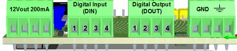
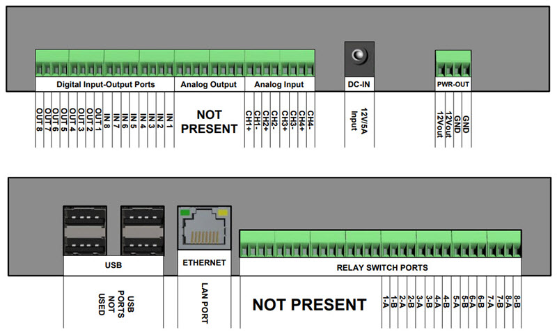
RIO device is produced in 2 Boards types:
RIO Board-0, embedded with 4 Digital Inputs and Digital Outputs.
| Tip |
|---|---|
Physical connection of RIO Board-0 is identical with RVS, please see: Section 3.12, “RVS connection”. |
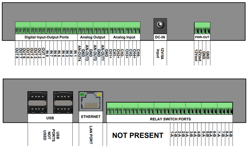
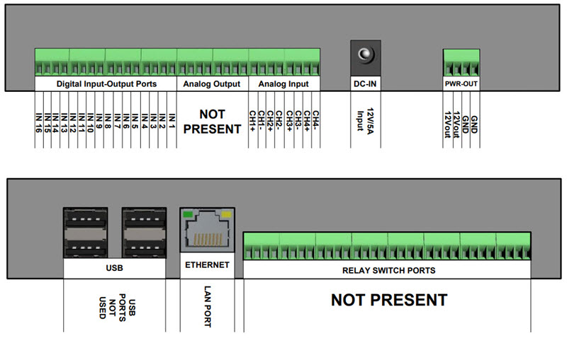
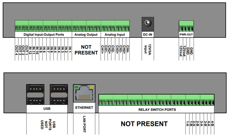
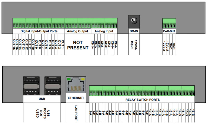
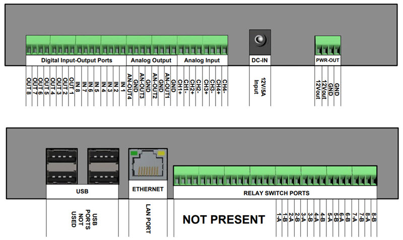
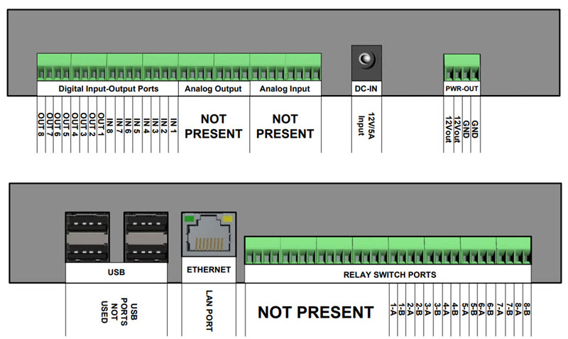
RIO Board-1, available in more subtypes.
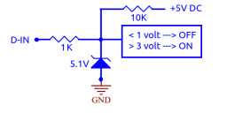
Digital Input (D-IN)The input ports are normally kept at 5V by means of a 10Kohm resistor. The logic value is ON. By connecting the input port to GND, the value goes OFF.
| Tip |
|---|---|
Interesting chapter: Section 3.13.1.2, “Connecting a motion sensor to Digital Input”. |
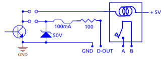
Digital Output (D-OUT)You can choose whether to use the relay output ("clean contact" A-B), or the output "open collector" supplying with power +5 ... +12V with a max current of 100mA.
| Tip |
|---|---|
Interesting chapter: Section 3.13.1.1, “Connecting an external relay to Digital Output”. |
Relay SwitchLimit values: max switched voltage 220V DC, 250V AC; max switching power 30W or 62W; switched current 1A. The ON logic value corresponds to the closed contact.
| Tip |
|---|---|
Interesting chapter: Section 3.13.1.3, “Connecting a DC motor to Relay Switch Port”. |
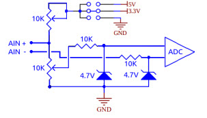
Analog Input (A-IN)These input ports are differential: they measure the
voltage difference between line + and line
- but it is necessary, however, that the
potential difference of each line with respect to GND does not
exceed 4.5 volts.
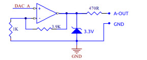
Analog Output (A-OUT)These output lines refer to GND. The output signal is adjustable between 0 and 10 V DC at 0.1V steps.
DC-INPower connector. Input 12V - 5A.
PWR-OUTPower sources for external sensors and actuators. The V-OUT is limited to 1A for each terminal. The GND must be used as a common ground reference for the various Input and Output lines.
LANEthernet 10M/100M auto-sensing. Support TCP/IP exclusively using the Abilis protocol.
USBWith the current firmware, ports are not used.
| |  | |
| 2.11. ELTI devices |  | 2.13. Ethernet devices |